Bend Loss Model
90 degree bends
The three Bend loss correlations are all for turbulent Reynolds numbers (Crane 1988Crane Co., Flow of Fluids Through Valves, Fittings, and Pipe, Technical Paper No. 410, Crane Co., Joliet, IL, 1988., A-29).
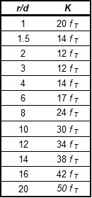
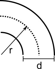
The K-factors for a smooth flanged bend with r/D ≥ 1 are provided in Table 1.
Table 1: K-factors for 90 degree smooth flanged bends
The standard threaded elbow is given by:

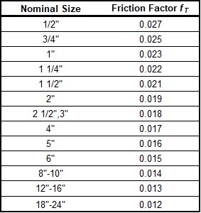
where fT is the turbulent friction factor given in Table 2.
Table 2: Pipe friction factors used for Crane formulas
The Mitre bend is given by:

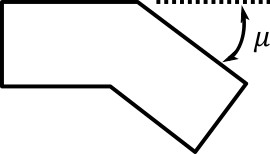
Non-90 degree bends
The two non-90 degree bend loss correlations are for turbulent Reynolds numbers (Crane 1988, A-29).
A smooth flanged bend with r/D ≥ 1 is given by:

where n is the number of 90 degree bends, K is the loss factor for one 90 degree bend (Table 1), and fT is given by Table 2.
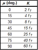
The Mitre bend is given by Table 3.
Table 3: K values for Mitre bends
Smooth Flanged Bends, r/D < 1
The smooth, flanged bend with r/D < 1 loss factor uses a correlation applicable for turbulent Reynolds numbers (Miller 1990Miller, D. S., Internal Flow Systems, 2nd edition, Gulf Publishing Company, Houston, TX, 1990., 209)
The loss coefficient is calculated based on Miller's class 2 bend model, which is sufficient for general design purposes, and is given by

C0 and Cf are assumed to be 1 for class 2 bends. Kb* is given by the nomograph on page 207 of Miller.
For r/D > 0.7 or Kb* < 0.4, CRe is given by Miller Figure 9.3. Otherwise, CRe is given by the equation below.

where the CRe for r/D = 1 is also found from Miller Figure 9.3.


