Tee/Wye Loss Model
Note: These correlations were developed for incompressible flow. K-Factors generally give good results when used in compressible flow, but there is uncertainty in this application. See the K Factor Loss Model topic for more discussion.
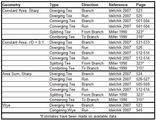
The loss factors calculated for tee and wye junctions involve complicated correlations that depend on the flow split, the ratio of flow areas, and the angle of the connecting pipes. The models used by AFT Arrow are taken mostly from Chapter 7 of Idelchik's Handbook of Hydraulic Resistance (Idelchik 2007Idelchik, I. E., Handbook of Hydraulic Resistance, 4th edition, Begell House, Redding, CT, 2007.). The equations will not be shown in this topic, but the references are given in the table below.
All tees and wyes have either diverging or converging flow streams. Two sets of equations are required for each configuration.
In the following discussion, the parameter Kc,s represents the loss factor based on the combined flow, stream flow area, and velocity for the side branch. Similarly, Kc,st is for the straight-through pipe (the run).
Figure 1 depicts the nomenclature. K-factor subscripts refer to base area reference and location in the Tee. For example, Kc,s represents the K-factor for the side branch (s) referenced to the combined (c) pipe flow area.
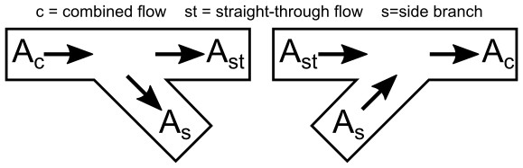
Figure 1: Idelchik’s nomenclature for diverging and converging flow through Tee/Wye junction
In the AFT Arrow Tee/Wye window, a simpler and more general nomenclature is used. AFT Arrow refers to the a, b and c pipes. This allows AFT Arrow to cover all the possibilities in Table 3 without specifying exactly which pipe is combined flow pipe. In some cases, you may not know all the flow directions in a system, and might not be able to specify which is the combined flow pipe.
AFT Arrow’s input method allows you to specify which pipe is the branch pipe. Idelchik calls this the "s" pipe for "side branch". AFT Arrow calls it the c pipe. If the tee angle is 90 degrees, it is not important which pipe you call the a pipe and which the b pipe. The distinction between a and b takes on more importance for non-90 degree pipes. In this case, AFT Arrow allows you to specify the angle of the branch pipe.
For tees/wyes the correlations used to calculate loss assume that the angle between the side branch and straight through flow pipes (labeled as As and Ast in Figure 2 above) can be at maximum 90 degrees. If the angle entered in the tee/wye junction exceeds 90 degrees between the side branch and straight through flow pipe, then the loss factor will be assumed to be equivalent to the loss with a 90 degree angle.
Figure 2 shows the Tee/Wye Properties window, with the Arrangement information at the bottom of the window. The a angle itself is specified on the Tee/Wye Model tab, where there are other options for how to model the tee.
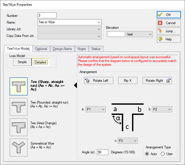
Figure 2: Tee/Wye Properties window allows you to specify the a, b and c pipes. The c pipe is always the branch pipe. This general method means you do not need to know the flow direction ahead of time.
Table 3: References for Tee/Wye junction correlations
Related Blogs


