Compressor/Fan Efficiency Data
Note: All efficiency data in the Compressor junction is treated as an isentropic efficiency.
Best Efficiency Point (BEP)
By defining a power or efficiency curve, the Best Efficiency Point of the compressor/fan can be found. Optionally, the calculated value can be overridden with a user-defined value in the Compressor/Fan Configuration window. It is generally desirable to operate compressors/fans as close to the BEP as possible. The Compressor/Fan Summary tab in the Output can display the BEP, and the % of BEP which indicates how close the operating point is to the BEP.
Nominal Efficiency
When modeling a fixed flow or fixed rise compressor/fan, you can optionally input a nominal efficiency as an approximation. This can be useful for sizing or design purposes, although more precise efficiency data should be entered when modeling a compressor/fan curve.
Power and Efficiency Calculations
Various stages of power or efficiency data relating to a compressor assembly can be added to a compressor junction.
The most basic value that can be accounted for is the compressor efficiency or power curve. This curve, entered in the Compressor Configuration window, is used to determine the power/efficiency being delivered to the compressor itself - the Shaft Power.
The Solver will determine the total pressure rise (Δp = p2 - p1) and volumetric flow (Q) through the compressor via iteration for the unique system. The isentropic power used at the compressor/fan, or the Ideal Power, can be calculated using the stagnation pressure values, volumetric flow, and isentropic expansion coefficient (k) as given by the following equation from Perry, 10-39 (1997)Perry, R. H., Green, D. W., Perry's Chemical Engineers' Handbook, 7th Edition, McGraw-Hill, New York, NY, 1997.:
where power is in hp, flow is in ft3/min, and pressure is in psia. Alternate forms of the above equation can be found in Perry.
Note: In Arrow's interface, gamma (γ) is used to represent the isentropic expansion coefficient instead of k.
With a compressor power or efficiency curve, the power required by the compressor/fan, or Shaft Power, can be calculated:
Note: The compressor efficiency value used here is the isentropic efficiency.
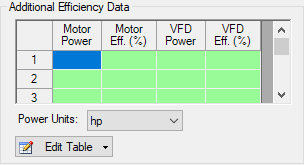
On a compressor's optional tab, further efficiency information can be defined:

Figure 1: Additional Efficiency Data
Entries in this table must come in pairs - both Power and Efficiency values must be present. For example, if Motor Power is entered, the Motor Efficiency column must also be entered. You can enter only motor data, only VFD data, or both.
Motor Power in this instance refers to the output power of the motor, which is equal to the Shaft Power calculated previously. This is because the motor driver is mechanically coupled to the shaft. Because the Shaft Power is already known, it can be looked up inside this table using linear interpolation, and the corresponding Motor Efficiency is used to calculated the Motor Input Power:
VFD Power is used in a similar fashion. The VFD Power in Figure 1 refers to the output power of the VFD, which is identical to the Motor Input Power (but instead of being mechanically coupled, this is represented by an electrical connection). Because Motor Input Power was calculated, VFD Efficiency can be found from the table using linear interpolation, and VFD Input Power can be calculated:
VFD Input Power is equivalent to the Overall Power, viewable in the Compressor/Fan Summary along with all of the other above values. Whenever an efficiency value is left undefined, it is assumed to be 1 (perfectly efficient).


