Sound Power Level
The Energy Institute identifies flow through sharp pressure drops as a primary cause of high frequency acoustic excitation in gas systems which increases the likelihood of equipment failure. This excitation produces high levels of noise but also high frequency vibrations in pipe walls that can lead to rapid fatigue and ultimately failure. Such points of failure are known to occur most often at welded discontinuities near the vibration source. Because this form of excitation and the resulting potential for failure may be especially intense within blowdown and relief subsystems, which are crucial to the overall system safety, it is important to predict the intensity of the excitation when designing the system.
This excitation occurs within pressure reducing devices, such as valves and orifices. The equation for calculating this high frequency acoustic excitation, also known as the Sound Power Level, is as follows (Energy Institute 2008Energy Institute, Guidelines for the Avoidance of Vibration Induced Fatigue Failure in Process Pipework, 2nd Edition, Energy Institute, London, UK, 2008. [Online]. Available: https://publishing.energyinst.org/topics/asset-integrity/guidelines-for-the-avoidance-of-vibration-induced-fatigue-failure-in-process-pipework., pg 60):


where PWL is expressed in terms of decibels, W is the mass flowrate in kg/s, P1 and P2 are inlet and outlet pressures, respectively, in units of kPa, T is the temperature at the junction inlet in Kelvin, and MW is the molecular weight in kg/kmol.
The SFF term is a correction factor for sonically choked junctions, as the sonic boundary generates additional noise and vibration.
Note: This calculation is for the Sound Power Level at the source and does not account for the location of the observer, the presence of sound insulation, or diffuser mufflers within the junction. For a full system noise analysis, other sources of noise such as compressors and turbulence in pipe flow should also be considered.
Note: Sound power level can be negative if the pressure loss or flow across the junction is sufficiently small. This is mathematically correct, but may be physically irrelevant.
Sound Power Level can be calculated for the following junction types:
-
Valve (Inline)
-
Orifice (Inline)
-
Bend
-
Area Change
-
Check Valve
-
Control Valve
-
Venturi
-
Screen
-
Relief Valve (Inline)
-
General Component
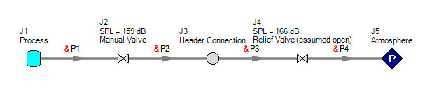
Figure 1: Calculated Sound Levels Displayed With Junction Names
Warnings and Design Alerts
A Design Alert can be set up for other thresholds if desired, but by default Arrow will display a warning when Sound Power Levels exceed 155 dB.
Note: This warning will only be shown when Sound Power Level is selected as an output parameter in Output Control.
The 155 dB threshold is important for its role in calculating Likelihood of Failure (LOF) due to high frequency acoustic excitation when using the method defined by the Energy Institute. When the PWL is greater than 155 dB, a user will need to determine whether the junction in question is a valve with low noise trim fitted. If so, the PWL will need to be corrected accordingly. When PWL at the source is greater than 155 dB, the LOF analysis proceeds with calculations of PWL at nearby welded discontinuities and mitigation efforts or changes to the process design may be in order.
Related Topics
Review of Compressible Flow Theory
Compressible Flow Theory in Single Pipes
Role of Pressure Junctions - Detailed Discussion (Long)
Chempak Technical Information - Detailed Discussion
Pipe Material Library References
The following junctions have a predicted Sound Power Level greater than 155 dB
Related Examples


