Control Valve
Control Valve junctions are always internal to the system, with two connecting pipes. This junction type allows modeling of valves that offer special pressure or flow control characteristics at a location in the pipe system.
The Control Valve Properties window follows the first of the two basic Properties window formats, displaying the connecting pipes in a fixed format. The Control Valve junction does not have an explicit flow direction, but adopts a flow direction from the connecting pipes.
Control valve types
You can model four types of control valves: Pressure Reducing Valves (PRV's), Pressure Sustaining Valves (PSV's), Flow Control Valves (FCV's), and Pressure Drop Control Valves (PDCV's). Loss information for a control valve is not required, because control valves are dynamic devices that change their geometry in response to the pipe system behavior. The loss that results is that required to maintain the control parameter. You can, however, specify the full open loss. This is the loss that will occur should the valve fail to a full open state.
-
A PRV is a device that controls the pressure in a pipe system. The PRV maintains a constant control pressure downstream of the junction as long as the upstream pressure exceeds the control pressure. If the upstream pressure is lower than the control pressure, the ability to control pressure is lost.
-
A PSV is similar to a PRV in that it controls pressure in a pipe system. While the PRV maintains a constant downstream pressure, the PSV maintains a constant upstream pressure. If the downstream pressure rises higher than the control pressure, the ability to control pressure is lost.
-
An FCV is a device that maintains a constant flow rate in a pipe system. By setting the junction to an FCV type and entering a flow rate, the junction will limit the flow through the connecting pipes to be equal to the control flow rate. The FCV can lose its ability to control flow when the pressure drop across it becomes zero or backward flow begins.
-
A PDCV is a device that maintains a constant (stagnation) pressure drop. For this option, the valve is never allowed to not meet its setpoint. An indicator that an unrealistic pressure drop has been demanded is a failure to obtain a converged solution.
PRV/PSV Static vs Stagnation Pressure
The control pressure for a PRV or PSV can be either static or stagnation (HGL or EGL for controlled Head). The default selection is static (HGL), as this is the most frequent application in industry.
Action if Setpoint Not Achievable
-
Always Control During Steady State - It is possible that a control valve cannot achieve a given set point. By default this option is off - this can be changed in the Parameters section of User Options. For additional information, see Control Valve Setpoint Not Achievable.
-
Use Default Actions - The behavior of the control valve when it fails can be modified by unchecking this option. The default behaviors represent the normal behaviors for the standard valve types.
Loss When Fully Open
By default, the valve will be set to model the valve with no loss if it fails open. This can be changed by choosing a loss model on the Control Valve Model tab to use Cv, Kv, or a K factor. When Cv, or Kv, is selected, the option becomes available to pull the value from an open percentage table on the Optional tab, and the option to apply an Opening/Closing Rate limit for the valve becomes available.
Open Percentage Table
The Optional tab allows data to be entered for special control valve characteristics. Specifically, the valve Cv and Flow Area can be Specified vs. the Open Percentage of the valve. This data does not affect AFT Impulse's flow solution. However, engineers frequently desire to know the valve's open percentage during operation to ensure it meets design requirements. The Valve Summary (in the Output window) always displays the valve Cv, and if data is specified for open percentage and flow area it will also display open percentage and flow area at the operating point.
AFT Impulse can assist in creating this Cv vs Open percent curve. This is accessible in the optional by by selecting "Edit Table" and then "Create Cv vs. Open Percent...". This then opens a window in which a user defined, linear, equal percentage, or Pre-defined curve can be defined and transferred to the Cv. vs. Open Percentage table.
Opening/Closing Rate Limits
If the default options for "Action if Setpoint is Not Achievable" are being used and the loss When Fully open is defined in terms of Cv or Kv, the maximum valve opening and closing rate limits can be specified. Rate limits allow the modeling of valves that have some type of limiting device which prevents the valves from opening or closing too quickly. If, during the transient, the pressures would cause the valve to open or close faster than the rates specified in the rate limits table, the valve's loss value will be set to the value dictated by the rate limits. If no rate limits are defined Impulse will assume that the valve will close or open instantly if it fails.
Transient Data
Control Valve transients provide two Transient Parameter options, Control Setpoint and Cv.
The Control Setpoint transient can be applied to adjust the control setting of the valve during the transient. For instance, a change in control pressure for a regulator valve can be modeled.
The Cv transient is intended to model a case where the control valve transitions to a static valve at a fixed Cv. For example, a control valve in a feedback loop for a pump may transition to a fixed open percentage when a certain pressure is reached at the pump discharge. Another case would be if a control valve were to be fully closed or fully opened in an emergency situation. Once a Cv vs. Time transient begins, the control valve will not be able to regain control.
If the valve Cv when controlling is within the defined Cv vs. Time data when the control valve transient begins, the control valve will begin at the corresponding point on the Transient graph and open/close from that point, rather than starting at the defined time zero. If the valve Cv when controlling falls above or below the defined table, the valve will jump to the closest point in the table, then proceed with the defined transient. For example, consider a defined closing transient which goes from a Cv of 200 to 100 as shown in Figure 1. If the valve is controlling at a Cv of 150, the valve will begin in the middle of the line at Cv = 150, then decrease to 100 (green line). If the valve Cv is 300 when the valve is controlling, then at the beginning of the transient the valve Cv will jump from 300 to 200, then follow the defined table until it reaches 100 (red line). If the valve is controlling at Cv = 50, then the valve will jump to a Cv of 100 and remain at 100 (purple line).
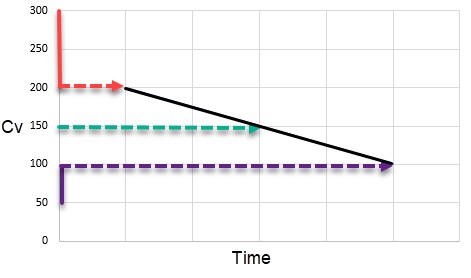
Figure 1: Example cases for Cv vs. Time defined for a closing valve
Control valve transients support single events. Thus the regulator pressure could be modified when some event occurred in the system.
For more information on transient data, including event transients, see Junction Transient Data.
Special Conditions
Control valves have two special conditions: to open fully and not control, or to close.
Related Topics
Related Blogs


