How Pressure Junctions Work
Pressure junctions (e.g., Reservoirs or Assigned Pressures) in AFT Impulse are an infinite source or sink of fluid. This means that they can draw or discharge as much fluid as is necessary to maintain the specified pressure. Some engineers have difficulty grasping this concept, and misuse pressure junctions in AFT Impulse. This section offers a physical example of how pressure junctions work to clarify for those having difficulty with the concept.
Consider the physical pumping system shown in Figure 1. This system pumps water from Lake Ontario to Lake Huron.
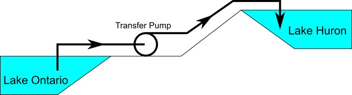
Figure 1: Physical pumping system to transfer water from shoreline supply tank (J1) to discharge tank (J2) at top of hill
An engineer is tasked with sizing the pump for this system. The engineer has an idea of the discharge head needed for the pump, and so builds an AFT Impulse model as shown in Figure 2. The Figure 2 model is attempting to represent the physical system in Figure 1, but it in fact represents the physical system in Figure 3.
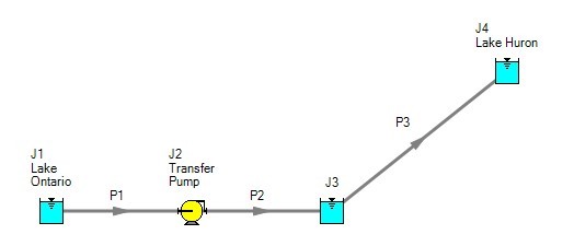
Figure 2: Model to size pump attempting to represent system in Figure 1. It does not accurately represent Figure 1.
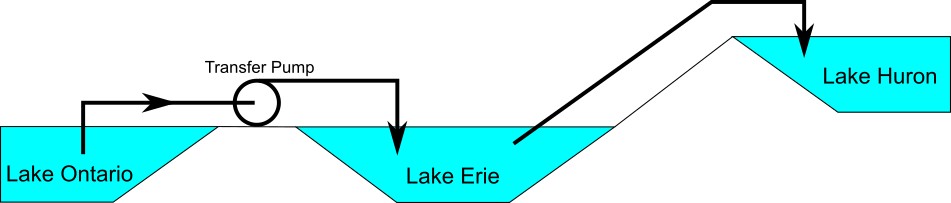
Figure 3: Physical system represented by model in Figure 2.
Why? Because the reservoir junction (J3), which is an infinite source of fluid, has been located between the pump (J2) and Lake Huron (J4). The J3 reservoir isolates Lake Ontario and the pump (J1 and J2) from Lake Huron (J4). The J3 reservoir is very much like placing Lake Erie between the supply and discharge piping.
If the engineer changes the surface elevation in J3, it is like changing the surface elevation of Lake Erie. It will change the flow rate in the pipes, but no matter how high the water level of Lake Erie, it does not change the fact that the pumping system is isolated from Lake Huron. The flow rate in the piping from J4 to J3 is entirely dependent on the difference in surface elevations between J3 and J4, and is not influenced by the J2 pump in any way.
How then should the physical system in Figure 1 be modeled? It should be modeled as shown in Figure 4.
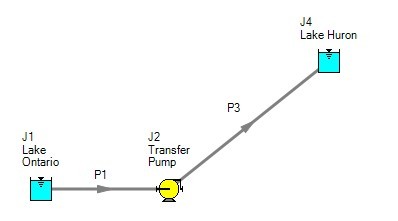
Figure 4: Proper model of physical system shown in Figure 1.
If the goal is to size the pump at J2, the model is Figure 4 can be used with the pump modeled as a fixed flow pump.


