Isometric
AFT Impulse allows the user to place pipe or junction objects anywhere in the Workspace.
In order to make building clean looking models easier, objects are snapped to the 2D Freeform grid by default. However, it may be convenient or desired to demonstrate the three dimensional nature of a system. A typical 2D grid has two sets of gridlines representing the x and y axes. An isometric grid has three sets of gridlines that are offset by 60°, representing the x, y, and z axes.
Enable the isometric grid by selecting Pipe Drawing Mode -> Isometric from the Arrange menu. There will be a prompt about converting non-isometric pipes - this is a required step, but may result in some unintended object placement. It is best practice to set the grid type before building a model and retain that type of grid if possible. It is also very helpful to show the Grid (Arrange -> Show Grid) when building an isometric model.
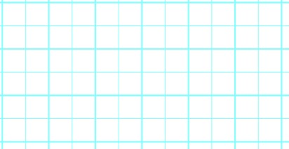

Figure 1: 2D (left) and isometric (right) grids
When drawing on the isometric grid, pipes are automatically segmented to lie on the gridlines as shown below. Dragging one of the handles on the pipe shows a preview line of where the pipe will be placed if adjustment needs to be made.
The placement of the preview line can be cycled through all possibilities by pressing the arrow keys or by scrolling the mouse scroll wheel.
Holding the alt key while dragging a pipe endpoint will retain the existing vertex and automatically add a new segment to the pipe - the placement of the line can be controlled with the arrow keys or scroll wheel as before.
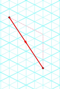
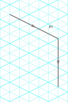
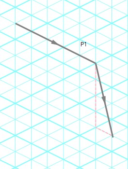
Figure 2: Automatic layout of isometric pipes
The default action is for pipes in the workspace to snap to the isometric gridlines. However, if desired, a given pipe can be set to not snap to the grid by clicking Edit -> No Snapping for Pipe or by right-clicking a selected pipe and clicking the Disable Pipes Snapping to Isometric Grid option.
Placing Junctions
Placing junctions onto the Workspace follows the usual rules - however, the visual appearance of the icon is more complex than in an orthogonal grid. When icons are added after pipes are placed, AFT Impulse will rotate the icon automatically following the workspace arrangement. When pipes are connected to icons already placed in the workspace, right-click and select Auto-rotate Icon to adjust the icon. For manual control of icon appearance, right-click and select Customize Icon to choose the desired appearance.
Note: It may be easiest to make use of the Rotate button in the Customize Icon window to find the appropriate icon. With many possibilities to choose from, finding the proper rotation can be difficult.
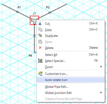
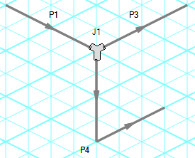
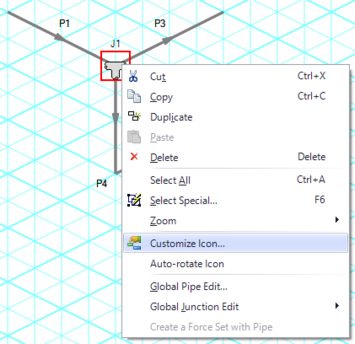
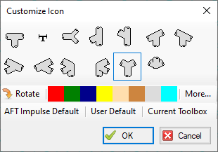
Figure 3: Icon rotations in isometric space
Related Blogs


