Check Valve Waterhammer Theory
Fluid Velocity at Valve Closure
Because a Cv is known in the models using either a user specified or estimated fluid velocity, the waterhammer theory for these is identical to a regular valve, except that the check valve closes when reverse flow occurs.
For the "Estimate from Fluid Deceleration" check valve, the fluid deceleration is calculated from the initial steady-state fluid velocity, the time at which the fluid begins to decelerate, and the time and velocity when the fluid first reverses through the valve by default. If a Deceleration Calculation Interval has been entered, this value will be subtracted from the time when reverse velocity begins to determine the time of initial deceleration (t,initial deceleration = t,reverse - Deceleration Calculation Interval). The velocity at this time will then be used as the steady state velocity.
For the Non-dimensional performance data, see the equations below.

Where:
-
Vsteady = Steady state fluid velocity
-
Vreverse = Fluid Velocity upon reversal
-
tinitial deceleration = Time at initiation of fluid deceleration
-
treverse = Time at fluid velocity reversal
-
Dpipe = Diameter of upstream pipe
-
V0 = Minimum fluid velocity to fully open the valve

Where:
-
Vmax,reverse = Maximum reverse velocity at which valve will close
The maximum velocity at which the valve will close is determined from the specified Maximum Reverse Velocity vs. Fluid Deceleration chart using the calculated fluid deceleration. As an example, see the chart in Figure 1.
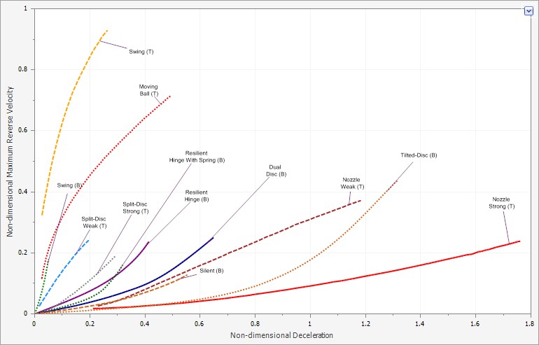
Figure 1: Non-Dimensional Fluid Deceleration vs. Maximum Reverse Velocity Chart with data from Thorley 2004(T) and Ballun 2007(B).
Force Balance (Swing Check Valve)
The swing check valve force balance model is solved using the torque balance equation, the valve equation, and the positive and negative characteristic equations.
From Wylie equation 6-42Wylie, E.B., V.L. Streeter & L. Suo, Fluid Transients in Systems, Prentice Hall, Englewood Hills, New Jersey, 1993., neglecting friction torque and any torques exerted by external ballast or springs (torsion springs on the disk pivot are included):

Where:
Tw = Torque due to the submerged weight of the disk
Te = Torque due to spring torque applied at the disk pivot point
Tp = Torque due to hydrodynamic pressures on the disk
I = Moment of Inertia of the disk about the pivot point
![]() = Angular acceleration of the disk about the pivot point
= Angular acceleration of the disk about the pivot point
Wylie equation 6-43Wylie, E.B., V.L. Streeter & L. Suo, Fluid Transients in Systems, Prentice Hall, Englewood Hills, New Jersey, 1993. for Tw :

Where:
W = submerged weight of the disk
L = distance from the pivot point to the disk center of gravity
α = Valve orientation angle (for inclined or vertical pipes)
From Wylie equation 6-44Wylie, E.B., V.L. Streeter & L. Suo, Fluid Transients in Systems, Prentice Hall, Englewood Hills, New Jersey, 1993. for Te :

Where:
S = torsional spring constant
θ = angle of zero spring torque
θs = current disk angle
From Wylie equation 6-46Wylie, E.B., V.L. Streeter & L. Suo, Fluid Transients in Systems, Prentice Hall, Englewood Hills, New Jersey, 1993. for Tp:

Where:
ΔP = pressure difference across valve, in psid
L = distance from the pivot point to the disk center of gravity
A = surface area of the disk
The valve equation (Equation 1) can be solved for ΔP as shown in Equation 2, which is substituted in Wylie 6-46:
|
|
(1) |

|
|
(2) |

Wylie equation 6-42 combined with the above equations becomes:

Along with the valve equation and the compatibility equations (Equations 3 through 5):
|
|
(3) |

|
|
(4) |

|
|
(5) |

These four equations can be solved for θ, ṁ, Pup, and Pdn.
Force Balance (Translating Nozzle/Plug Valve)
Similar to the swing check valve, the translating nozzle/plug check valve force balance model is solved using the force balance equation, the valve equation, and the positive and negative characteristic equations.
From Wylie equation 6-51Wylie, E.B., V.L. Streeter & L. Suo, Fluid Transients in Systems, Prentice Hall, Englewood Hills, New Jersey, 1993., neglecting friction force, and any force exerted by external ballast or springs (linear springs on the disk/plug are included), the force balance on the disk/plug is given by:

Where:
Fw = Force due to the weight of the disk/plug
Fe = Force due to spring applied to the disk/plug
Fp = Force due to hydrodynamic pressures on the disk/plug
M = Mass of the disk/plug and the mass of fluid that is moved
![]() = linear acceleration of the disk/plug
= linear acceleration of the disk/plug
Force due to the weight of the disk/plug is given by:

Where:
W = Weight of the disk/plug
α = Valve orientation angle (for inclined or vertical pipes)
The force due to spring applied to the disk/plug is given by:

k = Linear spring constant
Xs = Length of spring at zero force
X = Current disk/plug position
The force due to hydrodynamic pressures on the disk/plug is given by:

Where:
ΔP = pressure difference across valve, in psid
A = cross-sectional area of the disk/plug
The valve equation, can be solved for ΔP as shown in the swing check valve section and substituted into the hydrodynamic force equation above:

The mass of the disk/plug and the mass of the fluid that is moved is given by:

By substituting in the force equations and mass equation given above, Wylie equation 6-51Wylie, E.B., V.L. Streeter & L. Suo, Fluid Transients in Systems, Prentice Hall, Englewood Hills, New Jersey, 1993. becomes:

Along with the valve equation and the compatibility equations shown above in equations 3-5 in the swing check valve section, with Cv expressed as a function of X, these four equations can be solved for X, ṁ, Pup, and Pdn.
Check Valve Vapor Cavitation Theory
The check valve vapor cavitation model is identical to a regular valve for all three types of check valve models, except that it closes when reverse flow occurs.
Related Topics
Related Examples


