Spray Discharge Waterhammer Theory
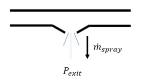
Spray discharge junctions (shown in Figure 1) model spray locations in a system. The spray junction discharges to a known pressure through an orifice or nozzle of some kind.

Figure 1: Spray discharge schematic
The relationship for pressure drop across the nozzle is as follows
where, for clarity,
![]() is defined positive flowing out of the system.
is defined positive flowing out of the system.
In addition, the spray junction is similar to a branch junction, so the following equation applies with the flowrate defined positive out.
where SC and SB are given by Equation 2 and Equation 3
.Combining the preceding equations and eliminating flow rate,
or
This is a quadratic equation, and the mass flowrate can be obtained by use of the quadratic formula.
Note: If the spray junction pressure falls below the exit pressure, reverse flow will occur. If the exit pressure is the atmosphere, the reverse flow will be air. However, Impulse assumes the inflow is at the pipe system density. This can lead to erroneous results if ignored. Reverse flow can be determined by graphing the flow at the spray junction or looking at the summary of maximum and minimum flows in the Output window.
Spray Discharge Vapor Cavitation Theory
When the calculated pressure at a Spray Discharge junction drops below vapor pressure, a vapor cavity forms at the junction. This is similar to a Branch junction.The vapor volume calculation is as follows:
where ṁspray is the spray outflow term. The ṁin terms are obtained from the positive compatibility equation, while the ṁout terms are obtained from the negative equation.
Similar to a pipe interior node, when the vapor volume is negative, the cavity collapses and the fluid pressure then rises above the vapor pressure.


