Force Theory
The force solution methods in AFT xStream are intended to calculate the unbalanced pneumatic loading on a series of axial aligned pipes rather than the total forces on those same pipes. Thus, most systems will see steady-state forces calculated as zero. However, systems such as an exit nozzle will see a non-zero steady state force, since there is a hydraulic force imbalance across that valve even at a steady flow rate.
It is important to keep in mind that AFT xStream is not a tool built for the analysis of pipe stress. In real systems, the configuration and location of supports, the deflection of pipes and components, and other effects of dynamic loading should be considered. All piping and components in AFT xStream are considered to be perfectly fixed in time and space, unless directed to change in a specified way, such as a valve closure. The forces that can be calculated by a hydraulic solver such as AFT xStream are only unbalanced hydraulic forces - not forces or stresses in pipe walls or supports.
Considering the above, the calculations for forces proceed under the following assumptions:
-
All piping and components are assumed to be completely rigid. No deflections or deformations are considered.
-
The force due to fluid and piping weight is neglected.
-
The volume of any junctions (bends, valves, etc.) is considered negligible. This is consistent with how junctions are modeled throughout AFT xStream.
-
All Difference Force sets comprise a pipe or set of pipes that are axially aligned between the beginning or ending nodes.
-
Both beginning and ending nodes for a Difference force set type are assumed to be 90 degree elbows.
-
The total force acting on the piping is assumed to be equal and opposite to the forces acting on the fluid.
Note: Forces calculated in xStream are always referenced as defined by the force set inlet and outlet. The reference direction for each pipe does not affect the forces calculated.
A complementary resource to this discussion is an AFT white paper titled Evaluating Dynamic Loads in Piping Systems Caused by Waterhammer, available on our website.
Difference Force Set Calculations
A Difference Force Set effectively represents the force between two elbows along a pipe. An example case for a difference force set can be considered for a stretch of pipe at constant elevation with a valve in the middle, as depicted in Figure 1 below.
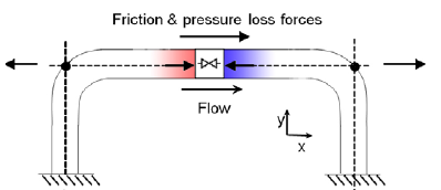
Figure 1: Simplified force diagram for fluid flow in a pipe
With flow through such a pipe, multiple forces act on the fluid, including friction, pressure, gravity (which AFT xStream neglects for force set calculations), normal forces from the pipe to the fluid, and forces due to changes in fluid momentum as flow is redirected through the elbows. Only forces which are axially aligned with the pipe will be considered.
Newton's second law relates these forces to the acceleration of the fluid, using the equation F=m*a. xStream uses this equation to determine the overall reaction force from the change in fluid velocity at each time step. Equation 1 below shows how xStream determines the force from the fluid acceleration.
|
|
(1) |

Using Equation 1 above, xStream takes the change in mass flow rate between the previous time step and the current time step to determine the change in velocity (and thus acceleration) of the fluid in each section to give the unbalanced force in each section. The total force for each pipe is then given by the sum of forces for all sections in a pipe.
In the steady state system, the total unbalanced hydraulic forces sum to zero, as the fluid has no acceleration, and thus no net forces acting on it.
Point Force Set Calculations
Point and Exit Force Sets in xStream represent the force caused by the pressure differential between the fluid and the ambient conditions. The Point force uses Equation 2 below. Note that this force is assumed to be applied over the flow area of the pipe. This assumption may not always be valid. For example, a blind flange would see the entire Point force, but a smaller tap on the side wall of a pipe would not.
|
|
(2) |

Exit Force Set Calculations
The Exit force captures the same fluid acceleration as the Difference Force Set, but also captures the force due to fluid exiting the system at the end of the force set. To do so, xStream accounts for the momentum change through the exit, as shown in Equation 3 below. Here, N is the final pipe section of the force set, connected to the exit.
|
|
(3) |

Note: Users of AFT Impulse may be familiar with the component-based approach Impulse uses to determine the total unbalanced hydraulic forces acting on a system. That approach has an implied assumption of constant density. Since the assumption of constant density in xStream does not hold true, xStream uses the approaches described above instead. If the approach implemented in xStream is used on an incompressible fluid in Impulse, the resulting forces are the same as those calculated using the component-based approach in Impulse.


