Importing Piping Component Files
AFT xStream includes the ability to import Piping Component Files (.pcf), which can be generated by a wide range of software, and provide a quick way to get started with the transient modeling portion of a project. Files can be imported into existing models.
Selecting File > Import Piping Layout From > Piping Component File (.pcf) brings up the Import Piping Layout Wizard in the Quick Access Panel, as shown below in Figure 1.
The Import Piping Layout Wizard is organized into sections that help guide the import process:
-
Folder Browser - After browsing to a folder, all .pcf files within the folder will be listed here. Simply clicking a file in the list will show a preview of the import in the Workspace. The location of the preview can be moved by dragging the icon in the upper-left of the selection area.
-
Object List - When a file is selected, the objects to be created will be listed here. Each individual object can be reassigned to a certain Junction, if the automatic assignment is not correct. For example, the originating software may have only had a "valve" while this could be a Relief Valve or a Control Valve. Changing the AFT Object type will change the preview in the Workspace. Right-clicking on an object shows a menu for converting object types.
-
Property Window - This button opens an additional panel that shows the raw properties for the currently selected object.
-
Link Materials - Opens the File Object Link window, where groups of pipes from the .pcf file can be associated with a pipe material, size, and type in the AFT Pipe Material library. Pipes can be grouped by file schedules (i.e. item codes) or diameters, and are sorted by length within each group. The selection from the AFT Pipe Material library will overwrite any diameter information from the .pcf file. Selections made for a .pcf material will be applied to all pipes that reference that .pcf material. Pipes associated with each material can be seen by clicking the arrow on the left expand the group (Figure 2) and can be edited individually or as a group.
-
Show Ignored Objects - Certain types of objects are ignored on import - these can be objects such as flanges, or additional file components such as materials or bolt specifications.
-
Options
-
Min Pipe/Max Pipe - Information fields on the length of the shortest pipe and longest pipe in the list of pipes to be imported.
-
Ignore Pipes of Length Less Than - Do not import pipes shorter than this amount.
-
Ignore Pipes of Diameter Less Than - Do not import pipes smaller than this diameter.
-
Ignored Pipes - How many pipes will be ignored based on the above settings. Ignoring pipes can be helpful in keeping a model clean and free of unnecessary components. For example, a pipe stress software may require many short pipe segments in between welds or flanges. However, these types of connections are almost always ignored for gas transient analysis. By ignoring short pipes, the amount of "import clean up" required can be reduced.
-
Preferred Scale - The wizard will Auto Scale the import by default. If a different scale is desired, this option can be disabled and a custom scale entered.
-
Show Pipes in Preview - Display the pipes in the Workspace preview.
-
Show Junctions in Preview - Display the junctions in the Workspace preview.
-
Combine Pipes When Possible - It is required that all pipes in the Workspace be connected by two junctions. However, this is not a requirement in all software. Therefore, some .pcf files may be generated with several pipes "end to end." If the pipes were imported this way, either junctions would need to be added, or the pipes would need to be manually combined, before the model could be solved.
-
Import Bends as Pipes - Pipe bends can be imported as junctions, or as a visual change in direction of the pipe. Importing bends as pipes is identical to using segments with assigned fittings and losses to show piping layout. To account for losses, bends will be matched to smooth flanged bends in the AFT Internal Fittings & Losses Library if an exact match for angle and r/D ratio is available and assigned to the pipe automatically. Losses that are not assigned automatically can be set up manually using junctions or fittings & losses. This option is helpful to reduce unnecessary model clutter and input if bend losses are negligible.
Note: In most cases, it is recommended to import bends as bends rather than pipes. Bends imported as bends will always use smooth bends with r/D and/or angle imported from the .pcf file and basis area inherited from the upstream pipe.
-
Ignore Fitting Lengths - Neglects additional length added to pipes that accounts for the equivalent length of fittings and losses, and is not actually part of the physical pipe length.
-
Import Data to Pipe or Junction Notes Field - Add the raw data from the originating file to the Notes tab of the corresponding object.
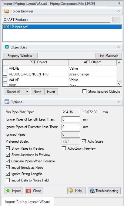
Figure 1: Piping Component File Import
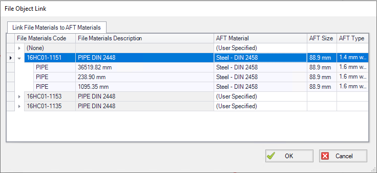
Figure 2: File Object Link window for Piping Component File Import
General Recommendations
Importing piping layouts from external file types such as Piping Component Files is intended to save time by allowing a means to quickly achieve a foundational layout. A .pcf file does not provide all information needed to create a working compressible flow model of a system and the import process will not produce a completed model or a perfectly accurate representation of the .pcf model. There will be missing data that must be assigned prior to analysis, such as fluid properties and boundary conditions. However, there are import practices and preparations that can be made to the .pcf file that will make creating model from an imported piping layout go more smoothly.
-
Workspace - Piping Component Files are a three-dimensional file format, whereas model layouts in the AFT Workspace are a two-dimensional representation of a system. Because the Workspace is a purely visual tool independent of actual system dimensions, the Scale/Flip Workspace feature can be useful for achieving a readable model when working with imported piping layouts.
-
Object Positioning - It is recommended to have some distance between most objects (this is not relevant to welds, branch/tap connections, gaskets, and supports). This aids in pipe connections, as objects that are very close together may have trouble connecting automatically. This is especially true of non-isometric models. Spacing between objects also streamlines the process of scaling objects on the Workspace after import.
-
Bends - By default, Import Bends as Pipes is unchecked, and importing bends as bends is recommended for the sake of model readability and a more flexible approach to incorporating bend losses. Bends that have common angles and r/D ratios present in the internal AFT library can be imported as Fittings & Losses automatically when importing bends as pipes, but other bends will need to be added manually as junctions, or have their losses specified using the Additional K Factor option in the Pipe Fittings & Losses window or as user-specified fittings & losses using the Fittings & Losses Library. When bends are imported as bends, they will be treated as smooth bends, the upstream pipe determines the cross-sectional flow area, and the r/D ratio and/or angle is imported from the Piping Component File. If only the r/D ratio or angle is specified, the other parameter will be calculated using the endpoint coordinates.
Note: Bends modeled explicitly can be joined with adjacent pipes as using Join Pipes/Junctions later if desired. Modeling bends as explicit junctions is advised for models containing bends that are not smooth flanged or have an uncommon angle or r/D ratio. Modeling bends as explicit junctions is recommended in xStream for more accurate modeling of compressible flow except when doing so would lead to unacceptable solver run times. When calculating forces between elbow pairs, modeling bends explicitly is always recommended.
-
Pipes - While the AFT Pipe Material Library contains many piping materials specified by ASME and ANSI, the Piping Component File format does not always contain these materials and material attributes can be defined within .pcf files in a number of drastically different ways. Because of this, materials, nominal sizes and schedules are not assigned automatically and can be assigned using Link Materials (shown above in Figure 2). Pipes can be grouped by file schedules (i.e. item codes) if they exist or by diameter so that pipe size and material can be applied to a group of pipes quickly. Pipe inner diameter is assigned from the nominal diameter defined in the pipe's coordinates within the .pcf file as a starting point, but any sizes assigned in Link Materials will override these inner diameters within the AFT model. Alternatively, pipes can be defined after import using Global Pipe Edit.


