Reciprocating Compressor
The reciprocating compressor is a subtype of Positive Displacement Compressor used to represent a compressor with flow driven by a crankshaft and pistons. This can be used to model both single and double-acting compressors with one or multiple cylinders in single, inline, V, or opposed configurations. The model incorporates the effects of cylinder geometry, crankshaft angles, and valve opening and closing angles into a thermodynamic model for gas expansion and compression. Gas compression and expansion within each cylinder is assumed to be isentropic and the valves are assumed to be lossless and open or close instantaneously. The options for configuring a reciprocating compressor are shown in Figure 1 below.
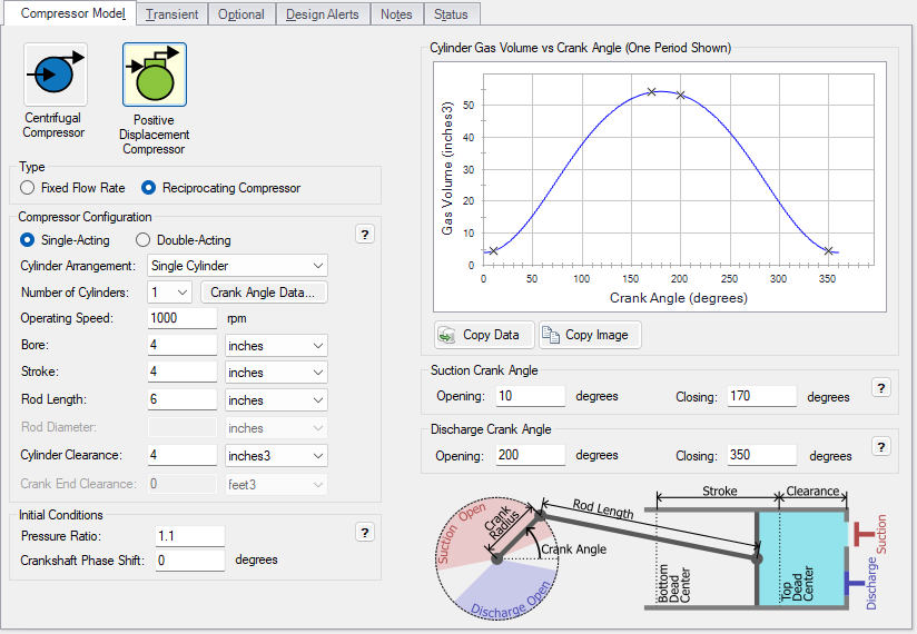
Figure 1: The Compressor Model tab of the Compressor/Fan Properties window for a reciprocating compressor
Compressor Configuration
The Compressor Configuration section of the Compressor Model tab has the following parameters:
-
Action
-
Single-Acting - This is used for compressors with a single compression chamber per piston where the connecting rod is outside the compression chamber.
-
Double-Acting - This is used for compressors with two compression chambers per piston where the piston rod passes through the chamber that is on the side of the crankshaft. The connecting rod connects the piston rod to the crank arm. The volume of the piston rod is subtracted from its associated chamber volume. See the Rod Diameter parameter below.
-
-
Cylinder Arrangement
-
Single Cylinder - The single cylinder option is used for single piston compressors or used when modeling each cylinder of a compressor separately, such as in multiple stage compressors or when building a model to capture manifold effects.
-
Opposed - An opposed cylinder arrangement has two banks of cylinders with a shared crankshaft separated from each other by 180 degrees. The cylinders in each bank operate in phase with their counterpart, and do not share crank arm angles between cylinder banks.
-
Inline - Inline cylinders share a crankshaft and move in parallel to one another.
-
V - A vee cylinder arrangement has two banks of cylinders with a shared crankshaft separated by an angle of 90 degrees. Crank arm angles are the same for each cylinder pair, resulting in a 90 degree phase offset between the first bank and the second bank.
-
-
Operating Speed - The operating speed is the crankshaft speed in RPM for the compressor in the current scenario.
-
Bore - The bore is the diameter of each cylinder.
-
Stroke - The stroke is the distance traveled by a piston between TDC and BDC.
-
Rod Length - The rod length is the length of the connecting rod between the rotational axes of the connections at the piston and the crank arm.
-
Rod Diameter (Double-Acting Only) - The rod diameter is the diameter of the piston rod, which connects the connecting rod to the piston in a double-acting compressor. This term is used is used to calculate the volume of the piston rod, which is subtracted from the gas volume for the chamber nearest the crankshaft.
-
Cylinder Clearance - The cylinder clearance is the volume of the compression chamber at TDC. In a double-acting compressor, this is for the compression chamber facing away from the crankshaft.
-
Crank End Clearance (Double-Acting Only) - In a double-acting compressor, this is the volume of the crank end compression chamber when the piston is at BDC.
The Crank Angle Data button lists the crank angle for each cylinder relative to the compressor's reference angle. For opposed and V cylinder arrangements, cylinder numbers alternate between banks so that even-numbered cylinders and odd numbered cylinders are in separate banks. The cylinder offsets for single-acting compressors are shown in Table 1.
Table 1: List of crank angle offsets for each single-acting cylinder in order of cylinder number based on the cylinder arrangement and number of cylinders
| Cylinder Arrangement | 2 | 4 | 6 |
|---|---|---|---|
| Opposed | 0,0 | 0,0,90,90 |
0,0,120,120,240,240 |
| Inline | 0,0 | 0,180,180,0 | 0,120,240,240,120,0 |
| V | 0,90 | 0,90,180,270 | 0,90,120,210,240,330 |
Note: The head ends of double-acting compressors have the same offsets, except each cylinder also has a crank end that is offset from its head end by 180 degrees.
Initial Conditions
-
Pressure Ratio - The pressure ratio is the ratio of the discharge stagnation pressure to the suction stagnation pressure for the reciprocating compressor. This is only used directly for steady-state calculations, and must be greater than one.
-
Crankshaft Phase Shift - This essentially offsets the phase of the crankshaft by shifting the reference crank angle. This can be used for offsetting the timing of multiple compressors from each other, which is useful when dealing with cylinder timings other than the defaults, for modeling reciprocating compressors with multiple compression stages, or modeling cylinders individually when modeling manifolds for a reciprocating compressor. This must be a positive number.
While the pressure ratio is not directly used in the transient solution, the steady-state solution is used to initialize the Transient Solver. The transient pressure ratio is dependent on the mass and energy entering the reciprocating compressor, the compressor configuration, and the stagnation pressures upstream and downstream of the compressor.
Disagreement between the transient and steady-state pressure ratios can contribute to artificial transients at the initial time steps of a model with reciprocating compressors.
Note: This can be reduced by observing the stabilized transient stagnation pressures and adjusting the steady-state pressure ratio accordingly. However, this may result in a lower pressure ratio than the real system due to reduced valve losses and will impact the accuracy of steady-state results.
Cylinder Gas Volume vs Crank Angle
The Cylinder Gas Volume vs Crank Angle graph shows one period of each compression chamber in the model, which is one period per cylinder in a single-acting compressor. This graph provides quick visual confirmation that the compressor is set up properly. The volume at each crank angle is determined from the cylinder and crankshaft geometry that are defined in the Compressor Configuration section, while the shift between the start of each compression chamber's cycle is determined by the Crank Angle Data values. Valve opening and closing events are displayed on each plot with X marks. The Crankshaft Phase Shift, if applicable, is shown as a vertical line at the crank angle defined by the shift.
The X-Y Data of the plot can be copied and will contain a series for each compression chamber and one series for valve timing events. An image of the plot can also be copied.
Crank Angles
Crank angles for valve events are defined relative to a crank angle of 0 degrees at TDC so that the suction stroke occurs before the discharge stroke, as shown in Figure 2.
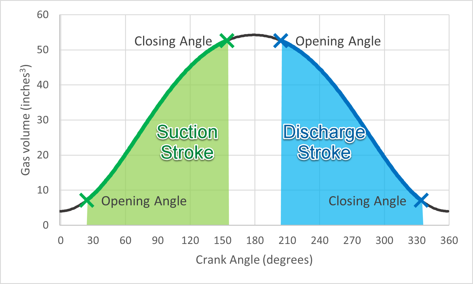
Figure 2: Illustration of suction and discharge strokes with crank angles
All cylinders within a compressor are assumed to obey the same valve timing relative to their individual TDC point (or BDC for the crank end of double-acting cylinders), and the valve angle set points must therefore be between 0 and 360 degrees.


