Air Distribution, Creating Libraries - ANS
Air Distribution, Creating Libraries - ANS (Metric Units)
Summary
This example focuses on creating Engineering and Cost Libraries for a system, then connecting the libraries to the model in order to obtain accurate results based on the cost data.
Note: This sizing for this example can only be completed if you have a license for the ANS module. However, the libraries can be built without access to ANS.
Topics Covered
-
Using external libraries
-
Building engineering and cost libraries
-
Using Scale Tables for cost
-
Connecting and using existing engineering and cost libraries
Required Knowledge
This example assumes the user has already worked through the Beginner: Air Heating System example, or has a level of knowledge consistent with that topic. You can also watch the AFT Arrow
In addition, it is assumed that the user has worked through the Beginner: Three Tank Steam System - ANS example, and is familiar with the basics of ANS analysis.
Model Files
This example uses the following files, which are installed in the Examples folder as part of the AFT Arrow installation:
-
Air Distribution.dat - engineering library
-
Air Distribution Costs.cst - cost library for Air Distribution.dat
-
Steel - ANSI Pipe Cost.cst - cost library for Steel - ANSI pipes
Step 1. Start AFT Arrow
From the Start Menu choose the AFT Arrow 9 folder and select AFT Arrow 9.
To ensure that your results are the same as those presented in this documentation, this example should be run using all default AFT Arrow settings, unless you are specifically instructed to do otherwise.
Open the US - Air Distribution - ANS Initial.aro example file listed above, which is located in the Examples folder in the AFT Arrow application folder. Save the file to a different folder.
Step 2. Create an Engineering Library
If it is desired to size any of the junctions in the system, such as the Compressors/Fans, the first step is to create an Engineering Library containing information for each of the components that will be sized. This engineering library can later be used to attach a cost library for the components. Engineering libraries can also be connected to future models to reuse any of the components in future systems.
To add a defined compressor to an engineering library:
-
Define the Compressor/Fan junction in the workspace.
-
For this example, the junction is already defined in the initial model.
-
-
Select the Compressor/Fan, go to the Library menu, and choose Add Junction to Library.
-
Give the Compressor/Fan a meaningful name such as Fixed Flow
If we had multiple Compressor/Fan models, valve types, etc. then we might need to add multiple Compressors/Fans, valves, etc.
The local user library is the default location where user defaults are placed for the local machine. If the junctions are stored in the local user library, it is possible to run all the calculations, and attach a cost library for the junctions. However, this restricts the use of the saved data, as the local user library cannot be shared with other users or be moved to different machines. Therefore, it is often preferred to place the components into an external library. Follow the steps below to move the components:
-
Open the Library Manager from the Library menu.
-
Click Create New Library at the bottom of the window.
-
Give it a unique filename, such as Air Distribution.dat. It is important to use a descriptive name to avoid confusion later if the library needs to be reconnected or sent to someone else.
-
Enter a Library Description. This is the name that will be displayed within the Library Manager itself and may be different from the file name. It is helpful to make the description the same name as the filename to avoid confusion. We will use the name Air Distribution for this library.
-
For the compressor that we added earlier, right-click the name, then click Move Content to move the junction from the LOCAL USER LIBRARY to the Air Distribution library. The Fixed Flow
-
Select Close to complete the process. If you open the folder where the library was created in step 3, the library file should now be available.
Note: The Copy option is also available if you want to preserve the items within the original library.
We are now ready to enter the cost data for the junctions in the model.
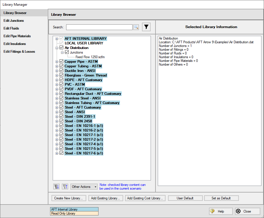
Figure 1: Library Manager showing the components moved to the new external library from the local user library
Step 3. Create a Cost Library for Junctions
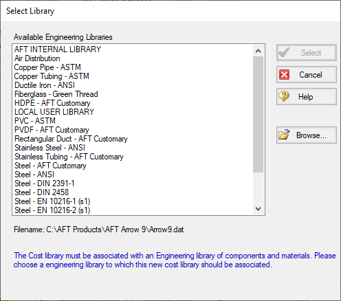
Use the Library menu to select Cost Library and open the Edit Cost Library window, which is used to create and view cost libraries. In this case we need to enter new cost data that we have obtained, so click New.
The list of Available Libraries should now be displayed as shown in Figure 2. Every cost library must be built of an existing engineering or pipe material library in order to link the cost information with the appropriate components in the model. Select to the newly created library, Air Distribution. You may need to use the Browse button to find it if the library is not shown in the list. Then click Select.
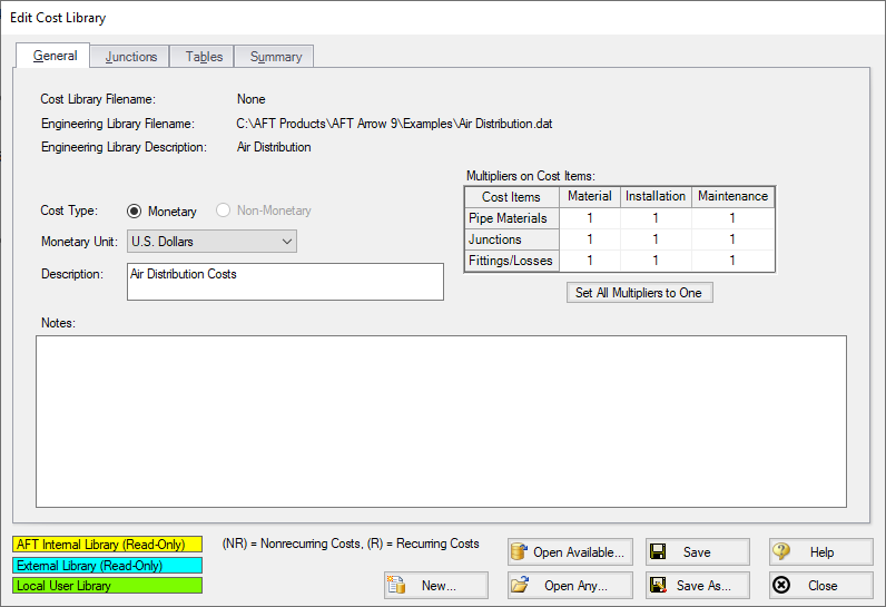
From here we will be brought to the General tab of the Edit Cost Library window. The description field is used as the name displayed within the Library Manager, similar with the engineering library.
The Notes field can be used to provide information on sources for the data, or other details which may be useful for tracking purposes and can be seen when reviewing the library contents in the Library Manager.
The other item of note is the Multipliers table. This can be useful to apply multipliers to account for inflation or uncertainty, without needing to calculate the costs directly. Note that multipliers can also be applied within the Assign Cost Libraries panel, so be cautious to avoid duplicate multipliers.
Ø In the Description field enter Air Distribution Costs, as seen in Figure 3. Now let’s move on to entering cost data. Click the Junctions tab to view the Junctions overview.
Within the Junctions tab each individual library item can be viewed under each Junction type. First expand the Compressor/Fan section by clicking the + icon and select the Fixed Flow
Note: The Show Engineering Data button can be used to view the properties window for the selected component in the engineering library.
ØClick the New Cost button to add an item to the table. By default, a cost item will be added that is configured for cost entry per item. Costs can be categorized as Material, Installation or Maintenance Cost Type. This categorization becomes useful if it is desired to exclude certain costs from the calculation or the sizing, but otherwise does not impact how the costs are calculated.
In the file explorer open the excel spreadsheet titled Air Distribution Costs - ANS.xlsx found in the Examples folder, and go to the
In this case we are sizing the compressor, so rather than having a cost for a specific compressor model, we have a range of costs specified based on the power requirement for the compressor. We will need to enter this data into the Tables tab first before we can define the cost item on the Junctions tab, so click on the Tables tab at the top of the window.
Ø Click the New Table button to begin defining the data table, and name it Compressor Material. Multiple Table Types are offered as the dependent variables for the table, which can either be plotted against a set of multipliers which will be applied to a specific data point, or directly against cost, as can be seen in Figure 4.
The data we have available is the cost for the compressor over a range of different power requirements, so choose Power and Cost as shown below, then click OK.
The new table name will now appear in the Tables list, and an entry section for Power vs Cost will become available. Copy the data in the excel spreadsheet for compressor material, then click the Edit Table button and choose Paste. Make sure that the table Units have been set to
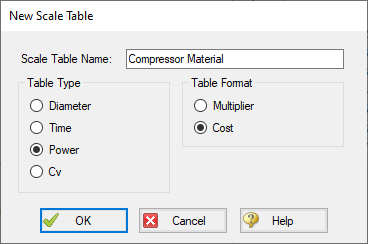
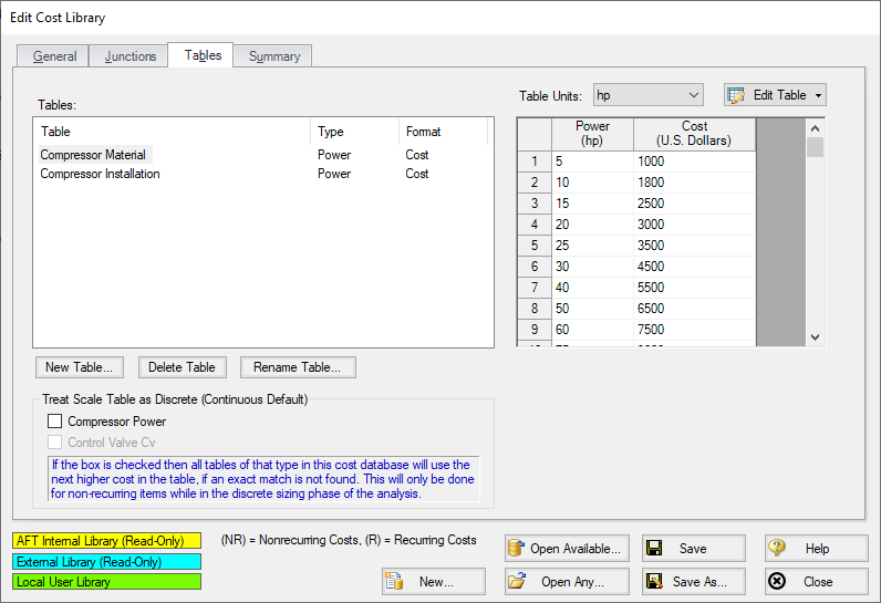
Figure 5: Complete tables list with material and installation cost tables for each of the junctions being analyzed
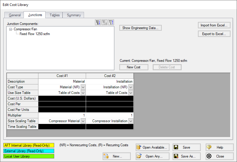
Now that the data tables have been created, we must assign them to the Compressor/Fan junction in the Junctions tab. Click on the Junctions tab and make sure that the Fixed Flow
-
For Cost #1 in the Description row, enter the name Material. This row is optional, but can be useful to provide clarification on the source of the entered cost.
-
The Cost Type should be specified as Material (NR), which is the default option. Note that NR denotes a non-recurring cost type, while R denotes a recurring cost type.
-
We want to use the Compressor Material table specified earlier, so next to Use Size Table select Table of Costs.
-
Select the Compressors Material table as the Size Scaling Table. Cost #1 is now complete.
-
Click New Cost to create a second cost item for the Compressor, and name it Installation.
-
Choose Installation as the cost type.
-
Specify Table of Costs for Use Size Table, then set the Size Scaling Table to the Compressor Installation table. The window should now appear as shown in Figure 6.
Click Save and give the cost library a name. We will use Air Distribution Costs.cst in this case. It is often useful to give the cost library a similar name to the engineering library to make transferring and reconnecting the library faster. Once you have finished saving the library, click Close.
Step 4. Create a Cost Library for Pipes
We now have costs for the equipment, but we still need costs for the pipes. Cost data for Steel-ANSI pipe from 1 to 20 inches are provided in the Excel spreadsheet opened earlier.
-
Open to the Edit Cost Library window again from the Library menu.
-
Click New
-
From the Available Engineering Libraries list, click Steel – ANSI.
-
Click Select to choose this library. You should now be on the General tab of the Cost Library window.
-
In Description, give the new pipe cost library a descriptive but unique name to differentiate it from the original library created for this model, such as Steel - ANSI Pipe Costs.
-
Go to the Pipe Materials tab. In the list section, we will be able to view all the sizes and types for the Steel - ANSI material. Under Sort choose Material, Type or Schedule, Nominal Size so that they will be sorted by type rather than size.
-
Expand the Steel - ANSI list, then expand the STD list (Figure 7).
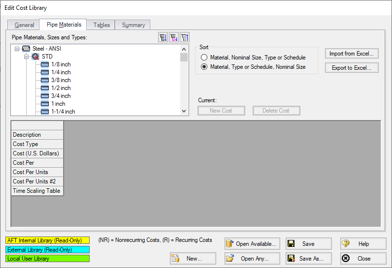
Figure 7: Pipe Materials tab in the Cost Library window showing the properties for the currently selected pipe
If a size from the list is selected, the hydraulic diameter can be viewed, along with a summary of the material, size and type. The New Cost button will also become active (Figure 7). There are a few methods available when adding the pipe costs. We could individually add the Material and Installation costs for each pipe size by selecting each size from the pipe materials list, then using the New Cost button to add these costs to the table individually. Alternatively, the pipe costs can be entered into a template in excel, then imported to the Cost Library all at once.
In this case, we have the Pipe costs available in a spreadsheet, so we will use the excel import/export option. To do this we will first export a template for the desired pipe sizes, then we will enter the cost information in the template and import the updated file as detailed below.
-
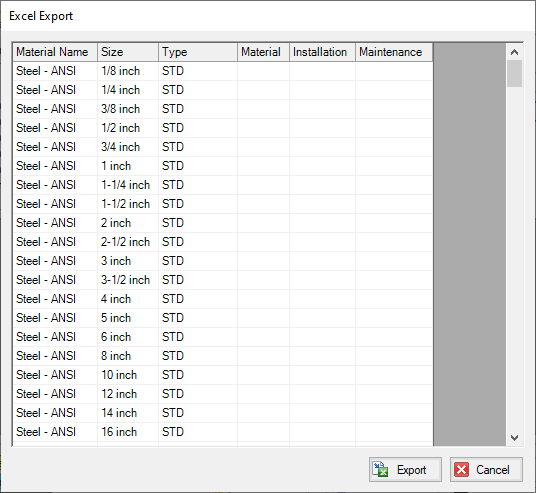
Make sure that the STD pipe material type is highlighted in the list, then click the button labeled Export to Excel on the right side of the window. The Excel Export window should be shown as in Figure 8, with all Steel - ANSI STD pipe sizes displayed.
-
Click Export, name the sheet, and save it to an easy to find location. The name does not matter, but we will need to be able to find this spreadsheet later to import back into the cost library.
-
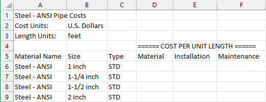
When Arrow has finished the export, a message will be displayed notifying the user of a successful transfer. Click OK, then browse to the exported worksheet and open it. The exported worksheet should contain a list of the selected pipe sizes, with empty columns where the cost per unit length can be entered for each cost type, as shown in Figure 9.
-
Open the Air Distribution Costs - ANS.xlsx spreadsheet with the costs for this example. Browse to the Pipe Costs tab and copy the Material and Installation costs for the 1 inch to 20 inch pipe sizes into the worksheet that we just exported. Ensure that data is entered for material and installation for each of the sizes from 1 to 20 inch, and that the length units are listed as feet in the worksheet, since these were the length units used by the manufacturer for their pricing. When this information is added back into the model where lengths are in meters, Arrow ANS will convert the cost/length information appropriately.
-
Save and close the worksheet.
Note: The length units used for the spreadsheet are taken from the default model units, which can be changed from User Options in the Tools menu.
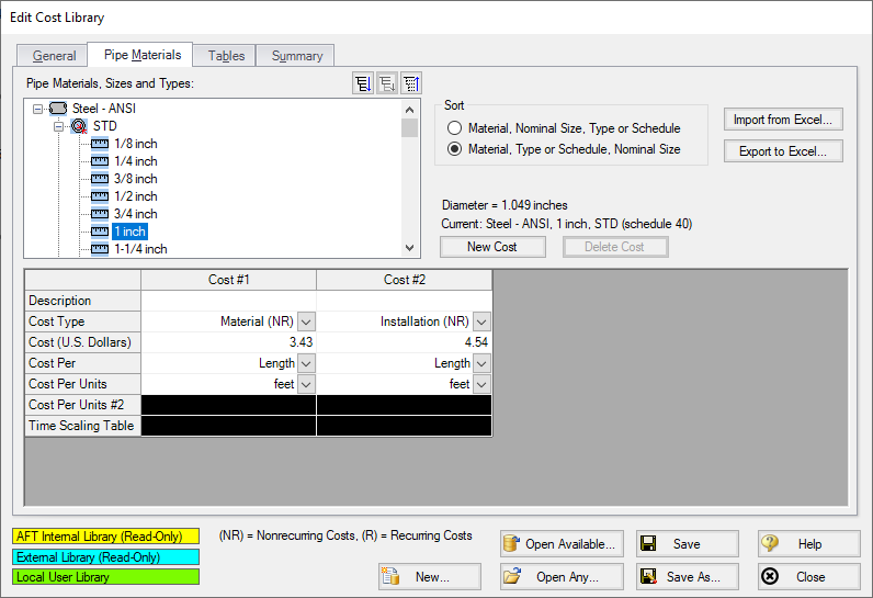
Back in AFT Arrow in the Edit Cost Library window, click the Import from Excel button, then browse to the worksheet we just updated and open it. When the Import has finished click OK on the notification from Arrow, then click the 1 inch pipe size under the Steel ANSI STD pipe type. The Material and Installation costs should now be filled in, as shown in Figure 10. Click Save to save the cost library with a unique file name (i.e. Steel - ANSI Pipe Costs.cst), select Yes to make the library connected, then close the window.
Note: When using the Export/Import features for the cost library, it is not required to enter information for every size that was exported in order to import the worksheet. It is important to not delete any headings or descriptive information for the pipe data that was included in the template. Worksheets can be exported /imported as many times as desired, but whatever data is in the spreadsheet will overwrite anything existing in the library, meaning that if the costs are left blank for a size, any cost information will be deleted for that pipe size in the library. Due to this fact it is recommended to export the current information in the library first before importing any change information so that an accidental overwrite does not occur.
Step 5. Connect the Libraries
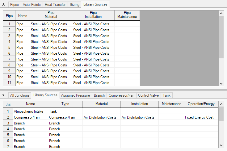
Open the Library Manager from the Library menu. Currently, the engineering library and two cost libraries should have automatically connected to the current model. In case they are not, we will now need to connect the libraries so that the junctions in the model will be linked to the costs and junctions in the engineering and cost libraries.
If the Air Distribution engineering library, Air Distribution Costs library, and Steel - ANSI Pipe Costs library are not connected to the model, follow the steps below to connect them.
ØChoose Add Existing Library at the bottom of the Library Manager window, then browse to Air Distribution.dat. Next choose Add Existing Cost Library and browse to Air Distribution Costs.cst then Steel - ANSI Pipe Costs.cst. This should make the libraries available, and automatically connect them, as shown in Figure 11.
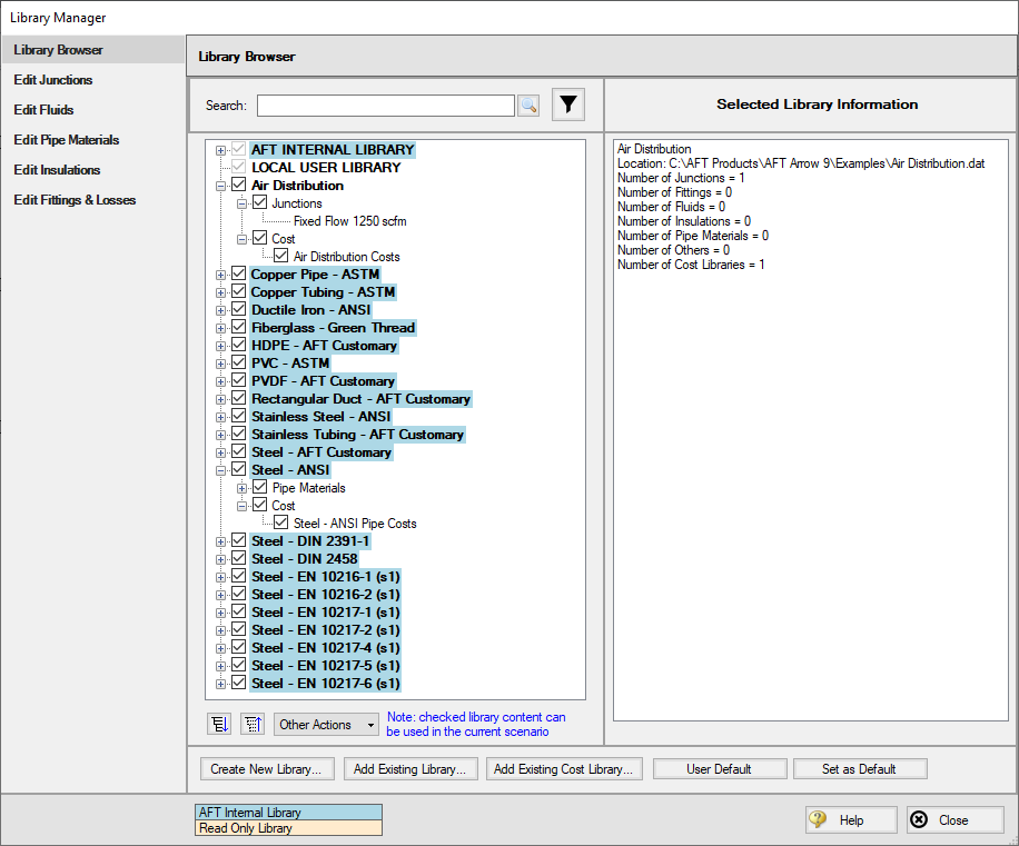
Figure 11: The Library Manager with the new cooling system engineering library and its associated equipment costs
Step 6. Define the Automatic Sizing Group
To make use of the newly creating engineering and cost libraries, a few inputs are required in the Sizing window. Go to this window now.
A. Sizing Objective
Go to the Sizing Objective panel. For the Objective, select Monetary Cost then select Calculate Cost, Do Not Size.
In the Options to Minimize Monetary Cost section, select the radio button to include Energy in Cost Report Only. The System Life and Energy Cost sections should now become available. Enter a System Life of 5 years and an Energy Cost of 0.11 U.S. Dollars Per kW-hr.
B. Size/Cost Assignments
On the Size/Cost Assignments panel, make sure the Pipes button is selected at the top. Click All on the bottom left then click Always Include in Cost at the top to add all pipes to the Include in Cost list.
Click the Comp./Fans button at the top to go to the Compressors/Fans size/cost assignments page. Select the radio button for J2 to Include in Cost Report Only.
C. Assign Cost Libraries
Go to the Assign Cost Libraries panel. All 18 pipes should be assigned to the Steel - ANSI Pipe Costs library. Go to the Comp/Fans page next and select Air Distribution Costs, as shown in Figure 12
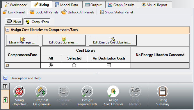
Figure 12: Applying the newly built cost library for the compressor on the Assign Cost Libraries panel
Note: Before running the model, be aware that there are no design requirements set for the control valves. When the solver begins to run, a Model Diagnostics window will appear to inform you that this may result in control valves adding pressure in order to achieve the setpoint. As you will see, the control valves will not add pressure, so this message is safe to ignore.
Step 7. Run the Model
Click Run Model on the toolbar or from the Analysis menu. This will open the Solution Progress window. This window allows you to watch as the AFT Arrow solver converges on the answer. Once the solver has converged, view the results by clicking the Output button at the bottom of the Solution Progress window.
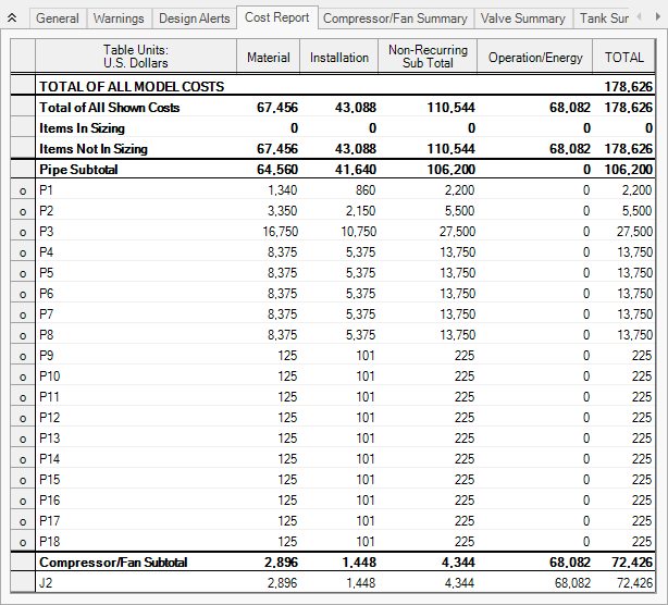
Step 8. Examine the Output
On the Cost Report, the total cost should be