Multiple Choking Points in Single Flow Path
It should be noted that sonic choking can exist in any multiple of the above geometries and at multiple locations in the same pipe system. AFT Arrow’s solution method incorporates this reality. The model shown in Figure 1 is that of a “triple choke steam flow”, where sonic choking occurs in three places, as indicated in Figure 1. The pressure drop in the system is as shown in Figure 2. The Mach number as it progresses down the system is shown in Figure 3.
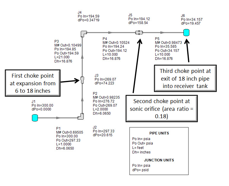
Figure 1: Steam flow in a pipe flow path with three choking points. Referred to as a Triple Choke Model. Solved using Mach March Method. Walters and Olsen (1997)Walters, T.W., and J.A. Olsen, "Modeling Highly Compressible Flows in Pipe Networks Using a Graphical User Interface," ASME International Joint Power Generation Conference, Denver, CO, 1997..
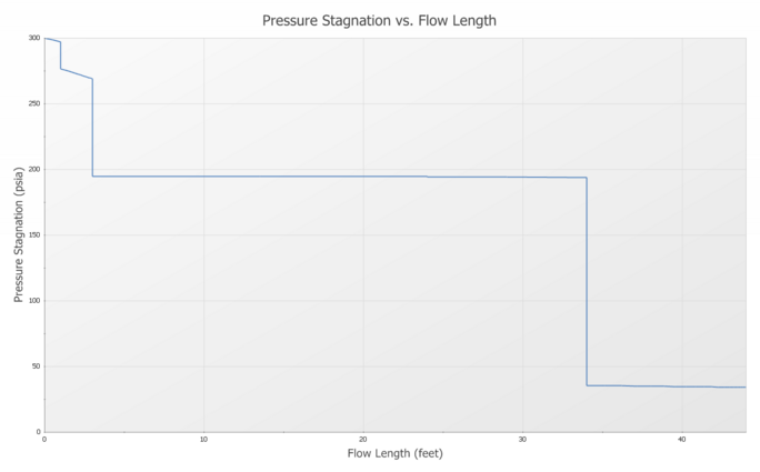
Figure 2: Stagnation pressure drop in Triple Choke Steam Flow model shown in Figure 1. Walters and Olsen (1997).
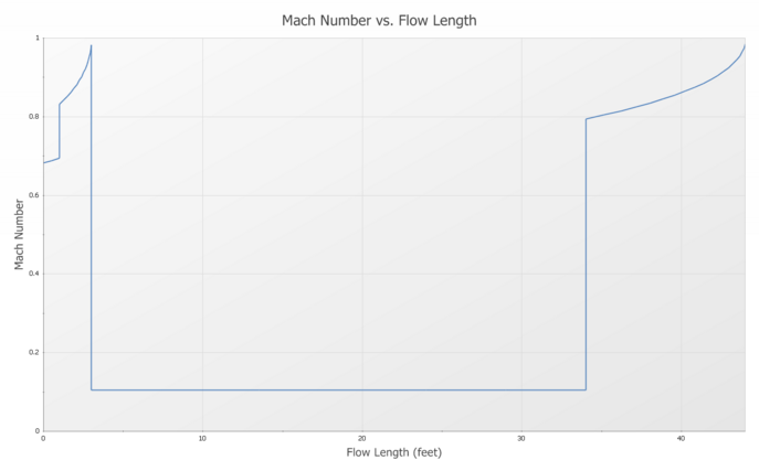
Figure 3: Mach number profile in Triple Choke Steam Flow model shown in Figure 1
Sonic choking in multiple locations in a flow path can be understood as follows. Recall that the sonic flow rate will have a unique value, given upstream conditions and the piping losses and thermal environment. No matter what happens at the exit boundary condition, the flow rate will not increase or change in any way. However, by changing the upstream conditions, the sonic flow rate can be changed. This is because the conditions are being changed on the upstream side of the choke point and can thus influence the fluid behavior.
To understand multiple sonic choking, consider the system in Figure 1. By iteration on flow rate it is determined that sonic choking will exist at the pipe expansion at junction J3. This fixes the flow rate for the entire system. This flow rate can then be entered as an upstream boundary condition on the remaining pipes. In this way the pressure can be obtained downstream of the choke point by iteration. After entering the flow rate as an upstream pseudo-boundary condition, it may turn out that sonic choking occurs again, such as it would for any pipe system with an upstream assigned flow rate. In this system the flow again chokes at the restricted area of an orifice at J5. Again, the known choked flow rate is used as a pseudo-boundary condition at the entrance to the pipe downstream of the orifice. Solving this pseudo system results in a third choking condition at the exit of pipe P5 as it connects to atmospheric pressure at J6. Choking also occurs as the flow exits the system.
The pseudo system that represents the triple choke system can be depicted as in Figure 4.
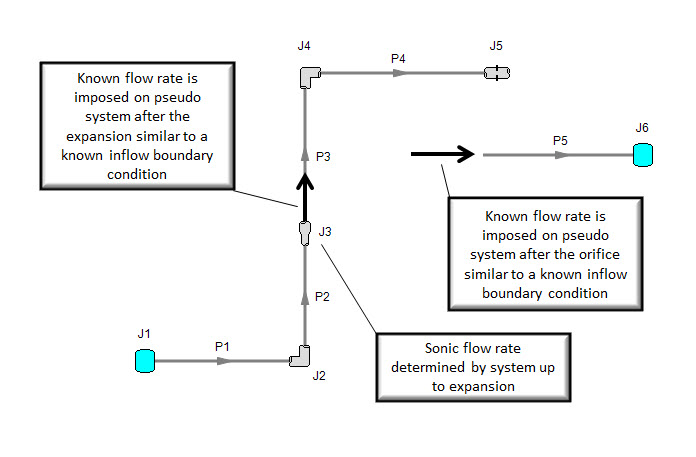
Figure 4: Triple Choke Steam Flow model pseudo system for determining pressure drops at choke points. Based on model shown in Figure 1. Walters and Olsen (1997).


