3-K (Darby) Method
The 3-K method described in Darby, 2001Darby, R., Chemical Engineering Fluid Mechanics, 2nd edition, Marcel Dekker, New York, NY, 2001., pp. 209-211, is used for high accuracy of predicted loss factors at low Reynolds numbers. The 3-K method is off by default, but can be turned on in Analysis Setup on the Junction Loss Models panel. This option enables the specification of textbook elbows and valves with their loss factor determined by the 3-K method. When this option is enabled the Elbow and Valve property windows change to Figure 1. There is now a drop down menu where the user can select from standard types of elbows and valves. After selecting an option in this menu the 3 K's will be displayed at the bottom of the properties window. These values come from the chart in Darby on pages 210-211. The user can also select User Defined in the 3-K (Darby) drop down menu to input their own values for K1, Ki, and Kd.

Where
-
Kf = Resistance coefficient
-
K1 = 3-K method constant
-
Ki = 3-K method constant
-
Kd = 3-K method constant
-
Re = Reynolds Number
-
Dn,in = Inner diameter
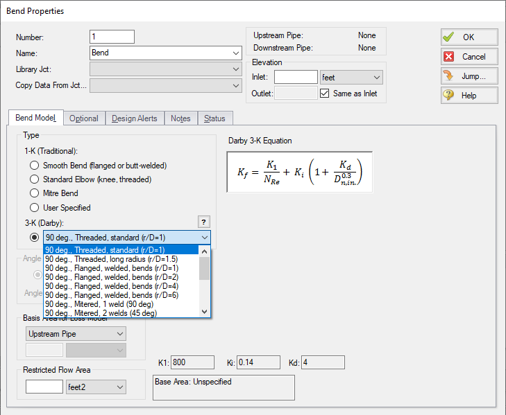
Figure 1: Bend Properties Window when 3-K method is turned on


