PAT Operation as a Turbine
The main function of the PAT model is to allow a pump to operate as a turbine. In this mode of operation, the PAT generates power by removing energy in the form of a head loss across the pump, compared to normal centrifugal pump operation where the pump adds energy in the form of a head rise across the pump.
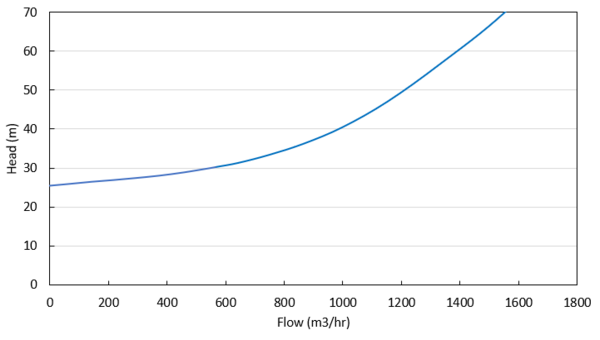
The turbine operating point is determined using the Turbine Performance Curve defined by the user. This curve relates head loss to flow rate similar to how the Pump Curve relates head rise to flow rate. Note that the PAT uses the turbine’s frame of reference for this data rather than the pump’s. Head loss and flow rate should be entered as positive values for the PAT. The Turbine Performance Curve should have a head loss greater than zero at zero flow and should see increasing head loss with increasing flow. An example Turbine Performance Curve is shown in Figure 1 below.

Figure 1: Example Turbine Performance Curve
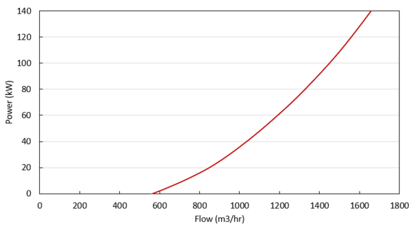
The power generated by the PAT is determined by the user-defined Turbine Power Curve. This curve relates power generated to flow rate, similar to how the Pump Curve relates pump power to flow rate. Note the PAT uses the turbine’s frame of reference for this data rather than the pump’s. The Turbine Power curve should have zero power generated at some non-zero flow rate and should see increasing power output with increasing flow. An example Turbine Power Curve is shown in Figure 2 below.

Figure 2: Example Turbine Power Curve
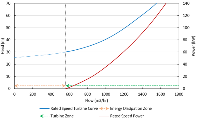
The flow rate at which the PAT generates zero power is called the ‘no load’ point. At this flow rate, the pump impeller is spinning with the fluid, neither adding nor removing energy from the fluid. At higher flow rates, the impeller’s speed is resisted by the motor, removing energy from the fluid and generating electricity. At lower flow rates, the impeller’s speed is resisted by the fluid, requiring energy to be added via the motor. These operating conditions are shown in Figure 3 below.

Figure 3: General turbine operating conditions
Related Blogs


