Pump as Turbine Overview
Running a pump as a turbine allows the pump to produce electrical power when the pump sees reverse flow. During reverse flow, the motor coupled to the Pump as Turbine (PAT) spins in reverse, causing the magnetic rotor to induce a current in the motor coils, turning the motor into a generator.
Note: The positive flow direction for the pipes connected to the PAT should be the direction in which flow will travel when the pump is operating as a turbine, rather than the direction in which flow will travel when the pump is operating as a pump. Thus, while the physical pump equipment will see reverse flow while operating as a turbine, the pump as a PAT will see positive flow.
Standard Turbine Curve
A Standard Turbine Curve is required to model a PAT and must include both head and power data. The head loss vs flow curve defines the head loss seen at the PAT while coupled to the motor and generating power. The power versus flow curve defines the power generated by the PAT while coupled to the motor and generating power.
To enter these curves, click Enter Curve Data. Previews of the applied curves can be viewed in the Standard Turbine Frame once the data has been defined.
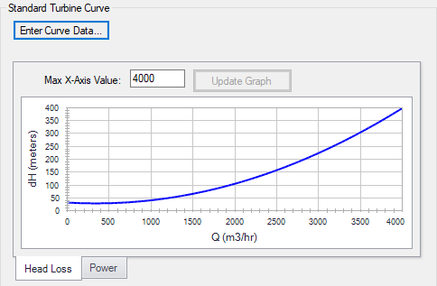
Figure 1: Standard turbine curve
Flow Directional Behavior
A visual representation of the modeled PAT is presented in the lower right of the properties window to provide immediate feedback on what the various options represent. In the PAT depicted in Figure 2, head loss and power information have been defined, and the PAT is in normal operation, with reverse flow seen at the pump.
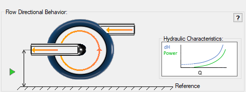
Figure 2: Flow Directional Behavior image for an example PAT
Related Blogs


