Housing Project (Metric Units)
Housing Project (English Units)
Summary
The objective of this example is to model a pipeline system to supply water to a new housing development. As the engineer you will evaluate the design to find the smallest pipe size that will still meet the water supply requirements.
No Fire Conditions:
Each house requires
Fire Conditions:
Each house requires
Topics Covered
-
Using Scenario Manager
Required Knowledge
This example assumes the user has already worked through the Beginner: Three Reservoir Problem example, or has a level of knowledge consistent with that topic. You can also watch the AFT Fathom Quick Start Video Tutorial Series on the AFT website, as it covers the majority of the topics discussed in the Three-Reservoir Problem example.
Model File
This example uses the following file, which is installed in the Examples folder as part of the AFT Fathom installation:
Step 1. Start AFT Fathom
From the Start Menu choose the AFT Fathom 12 folder and select AFT Fathom 12.
To ensure that your results are the same as those presented in this documentation, this example should be run using all default AFT Fathom settings, unless you are specifically instructed to do otherwise.
Step 2. Define the Fluid Properties Group
-
Open Analysis Setup from the toolbar or from the Analysis menu.
-
Open the Fluid panel then define the fluid:
-
Fluid Library = AFT Standard
-
Fluid = Water (liquid)
-
After selecting, click Add to Model
-
-
Temperature = 16 deg. C
-
Step 3. Define the Pipes and Junctions Group
At this point, the first two groups are completed in Analysis Setup. The next undefined group is the Pipes and Junctions group. To define this group, the model needs to be assembled with all pipes and junctions fully defined. Click OK to save and exit Analysis Setup then assemble the model on the workspace as shown in the figure below.
The fire hydrants are both turned off to begin the problem. Select the Optional tab in the Assigned Flow Properties window and select Flow Off to close the hydrant. Do this for both hydrants.
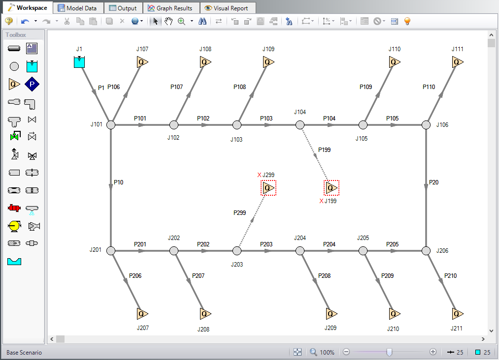
Figure 1: Model for Housing Project Example
Pipe Properties
All the mains are to be the same size. We will try 3, 3 ½ , and 4 inches to see which one meets the requirements. Enter 3-inch pipe for the main and hydrant supply lines in the base case.
-
Pipe Model tab
-
Pipe Material = PVC - ASTM
-
Pipe Geometry = Cylindrical Pipe
-
Size = Use table below
-
Type = schedule 40
-
Friction Model Data Set = Standard
-
Lengths = Use table below
-
| Pipe | Size | Length (meters) |
|---|---|---|
| 1 | 3 inch | 610 |
| 10 & 20 | 3 inch | 90 |
| 101-105 & 201-205 | 3 inch | 60 |
| 199 & 299 | 3 inch | 3 |
| 206 | 1 inch | 45 |
| 108 & 207 | 1 inch | 38 |
| 106, 110, 208, & 210 | 1 inch | 30 |
| 107, 109, & 209 | 1 inch | 22 |
Junction Properties
-
J1 Reservoir
-
Name = West Lake
-
Liquid Surface Elevation = 70 meters
-
Liquid Surface Pressure = 0 barG (0 kPa (g))
-
Pipe Depth = 0 meters
-
-
Branches
-
Elevation = Use table below
-
| Branch | Elevation (meters) |
|---|---|
| 203 | -3 |
| 102-105 & 204 | -1.5 |
| 101, 106, 202, & 205 | 0 |
| 201 & 206 | 1.5 |
-
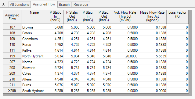
Assigned Flows
-
Elevation = Use table below
-
Type = Outflow
-
Flow Specification = Volumetric Flow Rate
-
Flow Rate = Use table below
-
| Assigned Flow | Name | Elevation (meters) | Flow Rate (m3/hr) | Special Conditions |
|---|---|---|---|---|
| 107 | Browns | 3 | 2.5 | None |
| 108 | Peters | 6 | 2.5 | None |
| 109 | Chambers | 10 | 2.5 | None |
| 110 | Fords | 4.5 | 2.5 | None |
| 111 | Kellys | 6 | 2.5 | None |
| 199 | North Hydrant | 1.5 | 20 | Flow Off |
| 207 | Norths | 6 | 2.5 | None |
| 208 | Stewarts | -4.5 | 2.5 | None |
| 209 | Coles | 9 | 2.5 | None |
| 210 | Allens | 3 | 2.5 | None |
| 211 | Burns | 1.5 | 2.5 | None |
| 299 | South Hydrant | 0 | 20 | Flow Off |
ØTurn on Show Object Status from the View menu to verify if all data is entered. If so, the Pipes and Junctions group in Analysis Setup will have a check mark. If not, the uncompleted pipes or junctions will have their number shown in red. If this happens, go back to the uncompleted pipes or junctions and enter the missing data.
The flows will be varied based on the different scenarios examined. To do this, we need to create child scenarios. We will use the Scenario Manager to create the designs we need to evaluate.
Step 4. Manage the Scenarios
-
In the Scenario Manager, create a child of this scenario by right-clicking on the Base Scenario and selecting Create Child. Name this child scenario 3 inch Pipe. This will be the parent scenario for all the runs with 3 inch main pipes. Alternatively, you can select the Create Child icon
 on the Scenario Manager on the Quick Access Panel to create this child scenario.
 -
Select the 3 inch Pipe scenario and create another child, this one named Fire Flow. set the flow rate at each house to
-
Next, create two children of this scenario named North Hydrant Fire and South Hydrant Fire. Load the North Hydrant Fire scenario from the Scenario Manager. Open the properties window of the North Hydrant and on the Optional tab, toggle the flow on by changing the special condition to None.
-
Now load the South Hydrant Fire scenario turn on the South Hydrant.
-
You now have all the scenarios that need to be evaluated for each pipe size but we still have two more pipe sizes that we need to investigate.
-
Right-click the 3 inch Pipe scenario and select Clone With Children.
-
Name this scenario 3.5 inch Pipe.
-
Repeat this process to create another set of scenarios named 4 inch Pipe. The Scenario Manager on the Quick Access Panel should look like Figure 2.
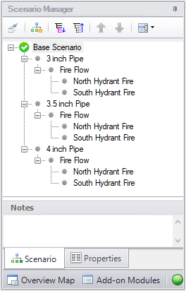
After creating the scenarios for the 3.5 inch pipe and 4 inch pipe, we need to open these scenarios and change the pipe sizes. This is accomplished most quickly with the Global Pipe Edit window.
-
Load the 3.5 inch Pipe scenario.
-
Select Global Edit then Global Pipe Edit from the toolbar or Edit menu.
-
Click the radio button for Pipe Template at the top, if not already selected, and click Select Pipe Data.
-
Change the Size to 3-1/2 inch, click OK.
-
In the Parameters to Change (Select in List) area, check the box next to Nominal Size 3-1/2 inch.
-
Since we only want to apply this to certain pipes, select Special above the Pipe List.
-
Change the Selection Type to Pipe Input Properties.
-
For Pipe Property, select Pipe Inner Diameter.
-
For Range, enter From 3 To 3.5 inches.
-
Click Select Pipes and note that 15 of 25 pipes were selected, these are all the pipes that are currently 3 inches. Click OK.
-
Click Apply Selections. A message should appear to inform you that changes were successively applied.
-
Click OK.
Repeat this process for the 4 inch Pipe scenario but changing the pipe Size to 4 inch. Return to the 3 inch Pipe scenario when finished.
Step 5. Specify Output
Before running the model, load the Base Scenario to set the Output Control. Open the Output Control window by selecting Output Control from the toolbar or Tools menu. This window allows the user to specify the output from the Fathom simulation. The window starts with a default set of outputs. Often the default output is sufficient. You may also specify a title for the model. Click on the General tab and add a title of Housing Project Example. On the Display Parameters tab, select the Junctions button and change the static and stagnation pressure units to
Now load the 3 inch Pipe scenario.
Step 6. Run the Model
Click Run Model on the toolbar or from the Analysis menu. This will open the Solution Progress window. This window allows you to watch as the AFT Fathom solver converges on the answer. This model runs very quickly. Now view the results by clicking the Output button at the bottom of the Solution Progress window.
Step 7. Examine the Output
The output from this model is shown in Figure 3. For the 3 inch Pipe scenario, with no hydrants open, the flow to each house is

On the Scenario Manager, load the North Hydrant Fire scenario under the 3 inch Pipe scenario. Run the model, and look at the output. This output is shown in Figure 4. Although the hydrant receives
Because we know that 3 inch is sufficient for No Fire conditions, we only need to test the Fire conditions for each pipe size. After testing all the fire conditions, 4 inch pipe is the only size that will deliver