NFPA Firewater System (Metric Units)
NFPA Firewater System (English Units)
Summary
This problem will walk you through building a hydraulic model of a fire water sprinkler system. You will then use trial and error to determine the hydraulically most remote spray nozzle.
In this example, a firewater spray nozzle system is hydraulically modeled. The system consists of 28 spray nozzles and is supplied by a fixed pressure source. As the design engineer, it is your responsibility to ensure that all spray nozzles receive at least
Topics Covered
-
Modeling a fire water spray system
-
Making groups
-
Using the NFPA feature
-
Generating an NFPA report
-
Using Excel Change Data
Required Knowledge
This example assumes the user has already worked through the Beginner: Three Reservoir Problem example, or has a level of knowledge consistent with that topic. You can also watch the AFT Fathom Quick Start Video Tutorial Series on the AFT website, as it covers the majority of the topics discussed in the Three-Reservoir Problem example.
Model Files
This example uses the following files, which are installed in the Examples folder as part of the AFT Fathom installation:
Step 1. Start AFT Fathom
From the Start Menu choose the AFT Fathom 12 folder and select AFT Fathom 12.
To ensure that your results are the same as those presented in this documentation, this example should be run using all default AFT Fathom settings, unless you are specifically instructed to do otherwise.
Step 2. Define the Fluid Properties Group
-
Open Analysis Setup from the toolbar or from the Analysis menu.
-
Open the Fluid panel then define the fluid:
-
Fluid Library = AFT Standard
-
Fluid = Water (liquid)
-
After selecting, click Add to Model
-
-
Temperature = 21 deg. C
-
Step 3. Define the Miscellaneous group
A valve in the model will use a loss model that is not enabled by default: Equivalent Lengths. To make this loss model available, navigate to the Miscellaneous group and to the Junction Loss Models panel. On this panel, select Include Equivalent Lengths and make sure
Enable NFPA calculations by opening the NFPA panel in the Miscellaneous group. Check the box next to Enable NFPA. Accept the default conditions and click OK to save and close.
Now that NFPA calculations have been enabled, you will need to direct AFT Fathom to use these calculations. To do this, click on the Analysis menu, select NFPA Configuration, then make sure Use is selected if it is not already. This should be the default selection after using the User Options to enable NFPA, but users should always double check.
Step 4. Define the Pipes and Junctions Group
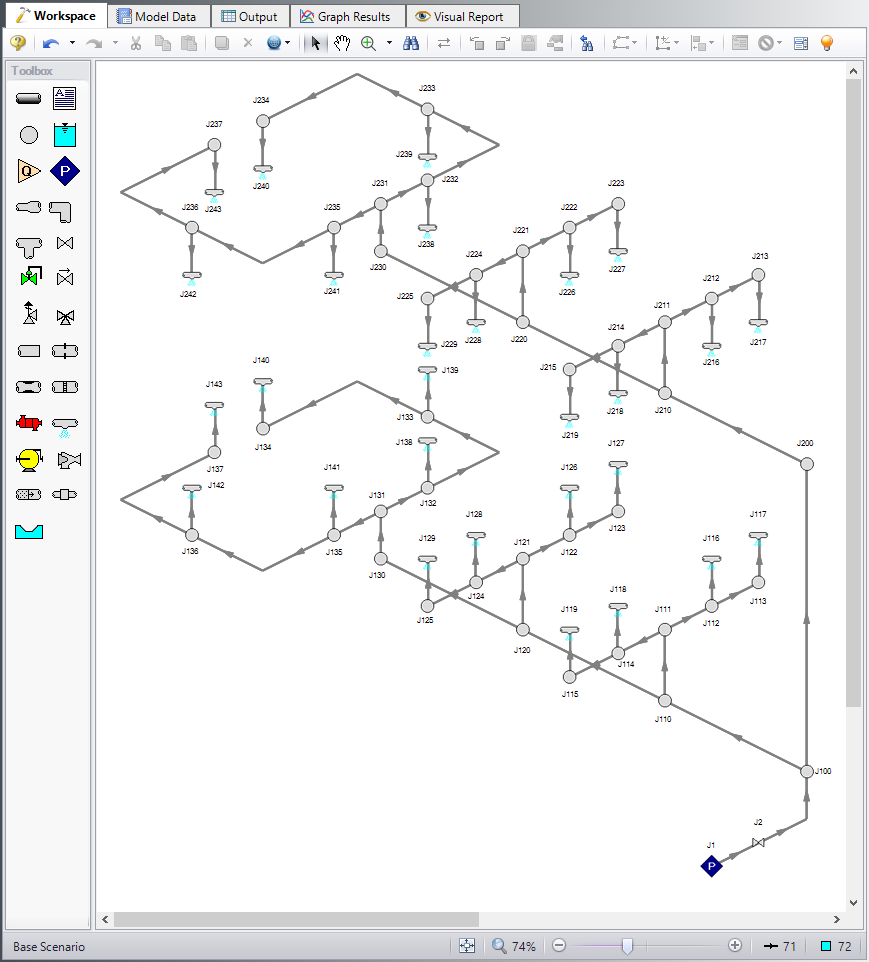
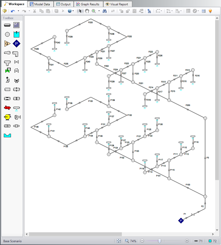
At this point, the first two groups are completed in Analysis Setup. The next undefined group is the Pipes and Junctions group. To define this group, the model needs to be assembled with all pipes and junctions fully defined. Click OK to save and exit Analysis Setup then assemble the model on the workspace as shown in the figure below.
It is imperative that you ensure that all pipe and junction numbers match what is shown in these figures so that the Excel Change Data used to input all information will be performed correctly.
Note: An Isometric grid can be turned on in the Arrange menu
The system is in place, but we now need to enter the properties of the objects. Because this model is large, all input has been added to a specially-configured Excel Change data spreadsheet that is included in the Examples folder and will be used to change the input to match the values in this example. Before importing this spreadsheet, it is necessary to define values in each pipe and junction because the Excel Change data spreadsheet is only capable of changing input data, not entering new data.
To quickly enter input data before using the Excel Change data spreadsheet, we will use the Global Pipe and Junction Editing features. If you are going to use Excel Change data to change the input you already have in your model, the values that you initially input in the model act simply as place holders and the value itself is not important. It is crucial, though, that you ensure that the units for each value that will be changed are specified correctly, because the Excel Change data spreadsheet will not change these units (it will only change the value itself).
Pipe Properties
To globally edit the pipes, select Global Pipe Edit from the Edit menu. Click All to select all pipes. Next, click Select Pipe Data and enter the following inputs in the pipe properties window.
-
Pipe Material = Steel - ANSI
-
Pipe Geometry = Cylindrical Pipe
-
Size = 1 inch
-
Type = STD (schedule 40)
-
Friction Model = User Specified
-
Data Set = Hazen-Williams Factor
-
Value = 120
-
Length = 3 meters
In the Parameters to Change section, click All to apply all changes to the selected pipes, then click Apply Selections at the bottom. Then click OK.
The fittings and losses data in the pipes needs to be entered manually in the Fittings & Losses tab. Use Table 1 below to enter these losses. You can use the Global Pipe Edit tool to expedite the process.
Note: Pipes that have Fittings & Losses entered in them will now have a red & displayed next to them. The symbol and display settings can be customized in User Options.
Table 1: Fittings and Losses for pipe input in NFPA model
| Pipes | Fitting Type | Quantity |
|---|---|---|
| 102, 112, 114, 122, 132, 133, 135, 200, 202, 214, 222, 224, 232, 233, 235 | Elbow, 90 deg. standard | 1 |
| 2, 136, 236 | Elbow, 90 deg. standard | 2 |
| 110, 111, 113, 120, 121, 123, 124, 131, 210, 211, 213, 220, 221, 223, 231, | Tee or Cross, (flow turned 90 deg.) | 1 |
Junction Properties
To globally edit the junctions, select Global Junction Edit from the Edit menu. Next, click the appropriate junction based on what you are inputting. For example, Spray Discharge. Click All to select all junctions in the list. Then, click Select Spray Discharge Data and enter the following inputs in the pipe properties window. Repeat this process for all junction types in the model using the inputs below.
-
All Spray Discharges
-
Elevation = 3 meters
-
Loss Model = K (Fire Sprinkler)
-
Exit Properties = Pressure
-
Exit Pressure = 0 barG
-
K (Fire Sprinkler) = 3 m3/hr per square root of bar
-
Number of Sprinklers = 1
-
-
All Branches
-
Elevation = 3 meters
-
-
J1 Assigned Pressure
-
Elevation = 1 meters
-
Pressure = 3 barG
-
Pressure Specification = Stagnation
-
-
J2 Valve
-
Inlet Elevation = 1 meters
-
Valve Data Source = Equivalent Length (Metric)
-
Equivalent Length = User Defined
-
Equivalent Length (User) = 4 meters
-
Import Excel Change Data
After you have input for all pipes and junctions, import the Excel Change data spreadsheet. To do this, import the spreadsheet in the Examples Help file entitled Metric - NFPA AFT Transfer Spreadsheet.xlsx by clicking on File > Import Excel Change Data, and then browsing to this spreadsheet. After all changes were made, a window will appear that lets you know that all changes were made.
Step 5. Create the NFPA Group
In order to generate an NFPA report, AFT Fathom needs to know the path for which you wish to generate the report. Generally, this report is developed for the hydraulically most remote path. If you have the GSC module, you can automatically determine which path is the hydraulically most remote (see the section below entitled Determining the Hydraulically Most Remote Path Using the GSC Module in order to see how to do this).
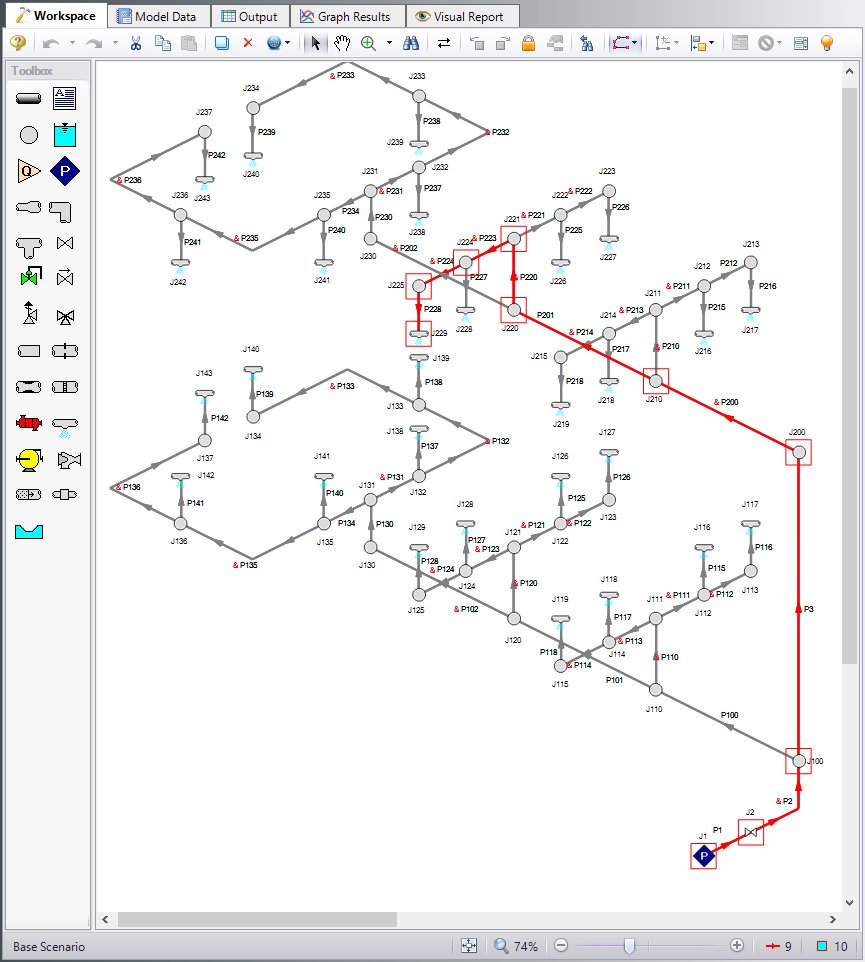
To create a group, select all pipes and junctions that are within the group. For this example, we know that the hydraulically most remote spray nozzle is J229. Therefore, select pipes P1, P2, P3, P200, P201, P220, P223, P224, and P228, and junctions J1, J2, J100, J200, J210, J220, J221, J224, J225, and J229 (see this path selected in Figure 2). Note, to select multiple objects, hold the shift key while selecting each with this mouse. Alternatively, you can select these pipes and junctions directly from the Group Manager. Once these pipes and junctions are selected, open the Group Manager by going to Edit > Groups > Manager. Click on Create Group and name the group NFPA Path. Make sure this path is selected under Existing Groups, then under both the Pipes in Group and Junctions in Group columns, select Workspace. Press OK to confirm this group.
The group we just selected contains the hydraulically most remote path, but this information was simply provided for the sake of convenience in this example and is not frequently known without modeling the system. If you have the GSC module, you can use it to determine the hydraulically most remote path. See the Example problem NFPA Firewater System - GSC if you are interested in seeing how to use the GSC module for this. Otherwise, if the hydraulically most remote path is not known, you will need to create a group for each spray nozzle path and determine which one receives the minimum flow at a fixed supply pressure.
Step 6. Specify the NFPA Path
Once you know the hydraulically most remote path, you will generate an NFPA report for this path. To specify which path in AFT Fathom you want to generate the NFPA report for, open Analysis Setup and go to the NFPA panel. Select the group in the Select a Group for the NFPA Report list.
Step 7. Run the Model
Click Run Model on the toolbar or from the Analysis menu. This will open the Solution Progress window. This window allows you to watch as the AFT Fathom solver converges on the answer. This model runs very quickly. Now view the results by clicking the Output button at the bottom of the Solution Progress window.
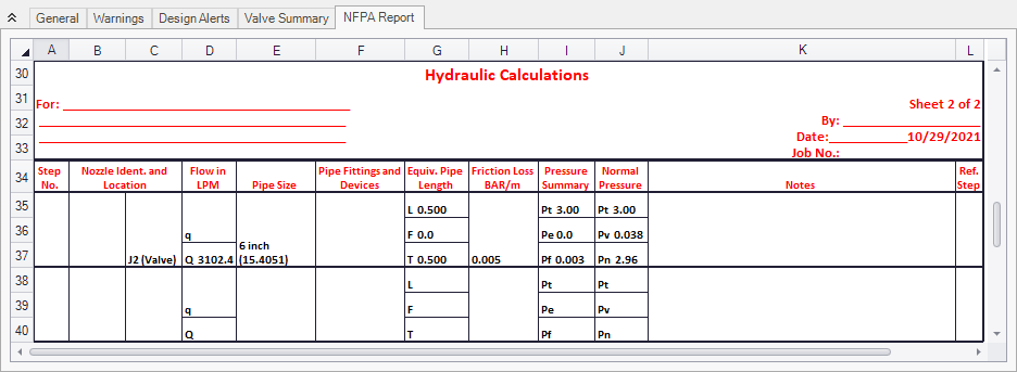
Step 8. Examine the Output
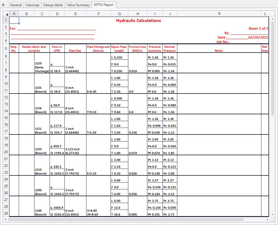
The Output window contains the NFPA Report, as well as the standard AFT Fathom output parameters. To view the NFPA Report, click on the NFPA Report tab in the General section of the Output window. You can expand this section by dragging the border down. The NFPA Report for this model is shown in Figure 3a and Figure 3b.
Conclusion
AFT Fathom allows you to display the hydraulic calculations for an NFPA report. In this example, you have built a model of a firewater system and generated an NFPA hydraulic report. Note that corrections in the reported flow are not necessary, because the flows reported in AFT Fathom are the true flow rates calculated not by general, simplified equations, but by using the fundamental equations of fluid flow.