Pump Trip with Accumulator (English Units)
Pump Trip with Accumulator (Metric Units)
Summary
This example shows the effect of adding a gas accumulator to reduce the down-surge after a pump trip.
Topics Covered
-
Using accumulator junctions
Required Knowledge
This example assumes the user has already worked through the Beginner: Valve Closure example, or has a level of knowledge consistent with that topic. You can also watch the AFT Impulse Quick Start Video (English Units) on the AFT website, as it covers the majority of the topics discussed in the Valve Closure example.
This model is based off of the Pump Trip with Check Valve example and model, and that example should be worked before this one.
Model File
Step 1. Start AFT Impulse
From the Start Menu choose the AFT Impulse 9 folder and select AFT Impulse 9.
To ensure that your results are the same as those presented in this documentation, this example should be run using all default AFT Impulse settings, unless you are specifically instructed to do otherwise.
Step 2. Open the Model
In reviewing the Pump Trip with Check Valve example it is observed that the pressure drops below atmospheric pressure along about
From the AFT Impulse examples folder make a copy of the US - Pump Trip with Check Valve.imp model file and save it to a new location. This model will be used as a starting point.
Step 3. Define the Pipes and Junctions Group
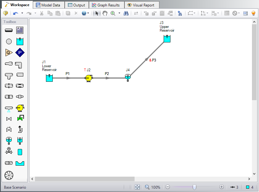
The Pipes and Junctions group is already defined, but some modifications are warranted. The model will be altered to resemble Figure 1.
Note: Instead of adding a new pipe to the Pump Trip model in order to add the accumulator, you can instead hold down Shift, then drag and drop the accumulator junction on the pipe to Split the pipe. This will allow you to add the junction, define the new length for each of the sections of pipe, and define which section of pipe the Fittings & Losses should be placed in.
Split pipe P2 into two pipes with a Gas Accumulator junction. For Pipe A, set the length to
Sizing and locating accumulators is very much a trial and error method. The typical assumption is that the accumulator should be located as near the source of the transient as possible. In developing this example, the accumulator was first placed
Therefore the accumulator was moved further away from the pump to see if this could be avoided. It was therefore first located at
The system is in place but now we need to enter the input data for the Gas Accumulator junction. Double-click the junction and enter the following data in the properties window.
Junction Properties
-
Gas Accumulator J4
-
Tank Geometry = Unchecked
-
Initial Gas Pressure = Calculate From Steady State
-
Initial Gas Volume = Known Volume
-
Value = 0.5 feet3
-
Polytropic Constant in Transient = 1.2
-
Max/Min Gas Volume = Unchecked
-
Flow Restrictor = Unchecked
-
Short Connector Pipe = Checked
-
Friction Factor = 0.018
-
Diameter = 4 inches
-
Pipe Length = 2 feet
-
Specify Elevation Change = Checked
-
Elevation Change = 2 feet
-
Junction Elevation = 10 feet
-

ØTurn on the Show Object Status from the View menu to verify if all data is entered. If so, the Pipes and Junctions group in Analysis Setup will have a check mark. If not, the uncompleted pipes or junctions will have their number shown in red. If this happens, go back to the uncompleted pipes or junctions and enter the missing data.
Step 4. Define the Pipe Sectioning and Output Group
ØOpen Analysis Setup and open the Sectioning panel. When the panel is first opened it will automatically search for the best option for one to five sections in the controlling pipe. The results will be displayed in the table at the top. Select the row to use one section in the controlling pipe.
Step 5. Run the Model
Click Run Model from the toolbar or from the Analysis menu. This will open the Solution Progress window. This window allows you to watch the progress of the Steady-State and Transient Solvers. When complete, click the Graph Results button at the bottom of the Solution Progress window.
Step 6. Examine the Output
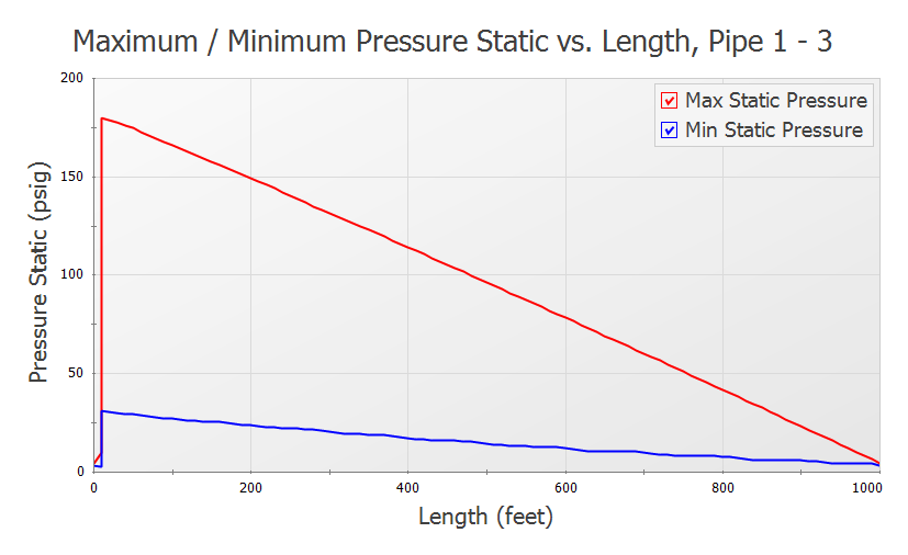
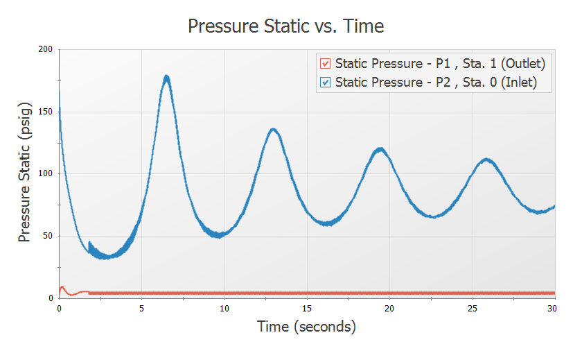
Graph the static pressure profile for all three pipes. This is shown in Figure 3. The pressure transient at the pump suction and discharge are shown in Figure 4. Note that the maximum pump discharge pressure has increased slightly above