Relief Valve
The Relief Valve junction allows users to model a valve that opens at a specified pressure in the system. Depending on how the relief valve operates, that pressure could either be the pressure at the relief valve inlet or the pressure at some remote point in the system. The differences between those valves are discussed below.
The Relief Valve Properties window follows the first of the two basic Properties Window formats, displaying the connected pipes in a fixed format. The Relief Valve junction adopts a flow direction from the connecting pipes.
There are three types of relief valves available:
-
Internal Relief Valve - Contains two connecting pipes and relieves into the downstream pipe. This type of relief valve acts like a regular valve that is closed until the specified pressure is reached.
-
Exit Valve - Contains one connecting pipe and relieves to an external ambient pressure when the specified pressure is reached.
-
Inline Exit - Contains two connecting pipes and relieves to an external ambient pressure when a specified pressure is reached. This type of relief valve acts as a lossless connection when closed and allows flow between the connecting pipes.
Opening and Closing Profiles
The Relief Valve junction has four different methods for the valve to open or close. There are also four preset valve profiles with a fixed combination of these methods that the user can choose from. These options are listed below.
The four methods by which the valve can open or close are:
-
Instant - The relief valve opens fully or closes fully from one time step to the next as the opening or closing conditions are met.
-
Time - The valve opens or closes according to a Cv vs. Time profile as the opening or closing conditions are met. The Cv vs. Time profiles are entered on the Transient tab, as needed.
-
Pressure - The valve passively opens or closes according to a Cv vs. Pressure profile as the opening or closing conditions are met. The Cv vs. Pressure profiles are based on the Valve Setpoints and the data entered in the Loss Model tab. Maximum Cv vs. Time rate limits can be applied.
-
Never - The valve never closes. This method cannot be applied to the valve opening.
The four preset valve profiles are:
-
Passive - The valve is set to open and close based on pressure setpoints.
-
Pilot Operated - The valve is set to open based on time and close based on pressure setpoints. Users must define an Opening Transient in the Transient tab.
-
Rupture Disk - The valve is set to open instantly when the set pressure is exceeded and never close.
-
Surge Anticipator - The valve is set to open and close based on pressure setpoints. This profile also sets the valve to use remote sensing with high and low pressure setpoints and with opening and closing Cv vs. Time rate limits.
The relief valve also has a General profile. This profile allows the user to customize the method by which the valve opens and closes. The only restriction placed on combinations of opening and closing methods is that if the valve opens based on pressure, it can only close based on pressure.
Finally, it is important to note that if the valve opens based on time and closes based on pressure, the valve cannot open faster than pressure at the valve allows. If the opening transient were to open the valve to a Cv larger than what the pressure at the relief valve dictates, the valve would immediately start to close. Thus, a time opening transient is effectively rate limited to what the relief valve inlet pressure dictates.
Balanced vs Unbalanced Valves
Relief valves can either be hydraulically balanced (constant backpressure) or non-hydraulically balanced. This characteristic of the valve is determined by how the dome of the relief valve is pressurized.
For an unbalanced valve, the dome of the valve is pressurized via the fluid downstream of the valve. Since the downstream pressure can change during the transient, the valve position is based on a pressure differential between the upstream and downstream pipes rather than based solely on the upstream pressure.
For the balanced valve, the dome of the valve is pressurized to a constant pressure, often by attaching some type of bellows device. With this system, the valve position is based only on the actual upstream pressure.
Valve Setpoints
The valve setpoints determine when the relief valve will open and when it will be closed. These setpoints can be defined using either pressure or head.
There are four possible valve setpoints the user needs to define:
-
Exit Pressure - The ambient pressure downstream of the relief valve for the Exit or Inline Exit valve types. This pressure will only be used to determine when the valve opens and closes when the relief valve is unbalanced.
-
Overpressure - The upstream pressure at which the valve is fully open. This input is only needed when the valve opens or closes based on pressure.
-
Set Pressure - The upstream pressure at which the valve opens. This input must be specified for all valve profiles and is replaced by the High and Low Pressure Setpoints when Remote Sensing is enabled.
-
Blowdown Pressure - The upstream pressure at which the valve is fully closed. All options for valve opening and closing require this input, with the exception of the Never profile. If the relief valve closes at the same pressure where it opens, the Set Pressure and the Blowdown Pressure should be set to the same value.
Note: The Relief Valve junction operates exclusively using stagnation pressure. All setpoints are defined as stagnation pressure and all calculations are based on stagnation pressure. In most cases, the assumption that stagnation pressure is equal to static pressure is valid.
Pilot Operation, Remote Sensing, and Surge Anticipation
The Relief Valve junction gives users the ability to model Pilot Operated Relief Valves (PORVs), Remote Sensing Relief valves, and Surge Anticipation Relief Valves. The PORV is enabled with the Pilot Operated preset profile, while the other options are available anytime the valve operates as a Passive pressure/pressure valve.
A PORV is a relief valve that can more rapidly respond to pressure surges. This rapid response is accomplished with two changes from a passive pressure relief valve. First, the pressure on both sides of the PORV’s plug is maintained at the upstream pressure via a pressure sense line (see Figure 1). Since the area above the plug is larger than the area below the plug, the net force on the plug acts to keep the valve closed regardless of pressure. Second, the valve is controlled by a Pilot. When the set pressure is reached upstream, the pilot acts to vent the dome of the valve (above the plug), rapidly changing the net force on the plug and opening the relief valve.
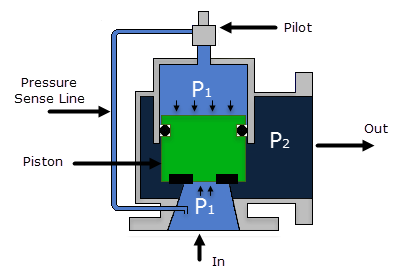
Figure 1: Pilot Operated Relief Valve Schematic
A Remote Sensing Relief Valve is a relief valve that opens based on the pressure at a specified location in the system other than the upstream side of the valve. This design allows the relief valve to be more responsive to surge events by opening the valve before the pressure surge arrives at the valve itself. The degree to which the relief valve is open is still determined by the pressure at the valve, but the pressure wave will be immediately relieved by the valve instead of first having to open the valve.
A surge Anticipation Relief Valve is a relief valve that opens when the pressure at a specified remote location in the system drops below a low pressure set point. These valves are typically paired with a pump and help mitigate high-pressure surges that are preceded by a low-pressure front. When the remote location’s pressure falls below the Low Pressure setpoint, the low-pressure pilot partially vents the dome of the valve above the plug. Then, if the remote location’s pressure rises above the High Pressure setpoint, the Surge Anticipation Relief Valve will behave the same as the PORV, opening based on the pressure at the relief valve inlet.
For the Surge Anticipation Relief Valve, the valve will only close when one of two conditions is met. The first condition is when the pressure at the valve falls back below the blowdown pressure and the valve is reset. The second condition is when the pressure rises above the High Pressure setpoint, the valve opens based on pressure, and then the pressure falls again, closing and resetting the valve. Effectively, if the remote pressure rises above the High Pressure Setpoint, the valve will behave as if it is a PORV and will not return to Surge Anticipation until the valve closes again.
Loss Model
The Relief Valve loss information is entered on the Loss Model tab. The available options change depending on how the valve opening and closing are defined. For all options, the Base Area for Loss Model can be specified, with the upstream pipe being used by default.
The following loss model options are available depending on which profiles are selected:
-
Instant/Time Profiles
-
Cv (Constant) - The relief valve instantly changes from closed to a fixed Cv.
-
Kv (Constant) - The relief valve instantly changes from closed to a fixed Kv.
-
CdA (Constant) - The relief valve instantly changes from closed to a fixed CdA. This CdA is defined as the product of an Orifice Effective Area (A) and a Discharge Coefficient (Cd).
-
The Orifice Effective Area can come from an API 526 ANSI/API 526 7th Edition - Flanged Steel Pressure-relief Valves, 2017, published by American Petroleum Institute, 1220 L Street, NW, Washington DC, USA letter designation or it can be User Specified.
-
The Discharge Coefficient must always be specified by the user. The value is typically specified by the manufacturer.
-
-
K Factor - The relief valve instantly changes from closed to a fixed K Factor.
-
Pressure Profiles
-
Cv (Variable) - The relief valve moves between the closed and open states with the Cv varying between 0 and the Fully Open Cv value.
-
Kv (Variable) - The relief valve moves between the closed and open states with the Kv varying between 0 and the Fully Open Kv value.
The Variable Data option for the Relief Valve Loss Model allows users to model the valve losses based on where the valve is between fully open and fully closed. The Linear based on setpoints option has Impulse determine those losses solely based on the setpoints the user has specified. If the user knows enough about the valve to describe a detailed loss profile, they can select the Non-linear option. The first data point must have a loss value of 0 at the Blowdown pressure. The final data point must have a loss value equal to the Fully Open loss value, at the Overpresure. The entered data is interpolated during the transient simulation.
Users can also define Rate Limits for valves that open or close based on pressure. These limits allow the user to restrict how fast the valve can change position. Some relief valves may have hardware in place to limit valve movement, other relief valves may have enough mass that their inertia prevents them from immediately responding to pressure changes.
Transient Data
Transient Cv, Kv, or K Factor vs. Time data can be entered on the Transient tab when the valve opens or closes based on time.
For a valve that opens and closes based on time, the transient data will be used exclusively to determine the valve’s position. If the valve opens based on time but closes based on pressure, the valve position will be limited by the pressure at the valve during the opening transient. The valve will switch to passive pressure control and remain at passive pressure control if the Loss Factor vs. Time data would cause the valve to open past what the pressure conditions dictate.
For more information about how to create Loss Factor vs. Time tables based on Open Percent data, please see the Valve Properties Window page.
Special Conditions
The relief valve has two Special Conditions:
-
Failed Open - The valve is forced to remain open regardless of pressure conditions.
-
Ignore Relief Valve - The valve is forced to remain closed regardless of pressure conditions.
For more information see Special Conditions.
Related Topics
Typical Approaches to Reducing Transient Pressures
Relief Valve Waterhammer Theory
Related Examples
Related Blogs
Looking to relieve pressure? Let's talk about Relief Valves in AFT Impulse


