Verification Case 12
PRODUCT: AFT Impulse 9
TITLE: ImpVerify12.imp
REFERENCE: Efficient Calculation of Transient flow in Simple Pipe Networks, 1992, Journal of Hydraulic Engineering, Vol. 118, No. 7, No. 26648, July, Karney, Bryan W. and McInnis, Duncan, pp. 1022-1030
FLUID: Water
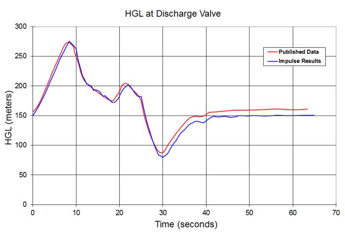
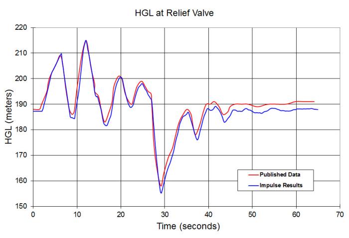
ASSUMPTIONS: Karney uses a relief valve connected to 3 pipes which discharges to atmosphere. AFT Impulse does not support a relief valve with this configuration. Thus an additional pipe (called P8) is used and made as short as possible without increasing pipe sectioning. The relief valve at J6 is then located at the end of pipe P8.
RESULTS:
DISCUSSION:
This model represents the solution for how a network responds to changes in a control valve. Differences between the published results and results from AFT Impulse may be attributed to the differences in how the relief valve is modeled in AFT Impulse, as is discussed in the assumptions above.


