Turbine
The Turbine Properties window follows the first of the two basic Properties window formats, displaying the connecting pipes in a fixed format. A flow direction through the junction is adopted from the defined directions of the connecting pipes.
The AFT Impulse turbine junction is intended to model a hydroelectric turbine, in which hydraulic power is converted to shaft power, which drives an electric generator. There are many different hydro-turbine designs, but they are generally placed into one of two categories:
-
Impulse-Type Turbine (e.g. Pelton Wheel)
-
Reaction-Type Turbine (e.g. Francis or Kaplan)
AFT Impulse models only the reaction-type turbine; specifically, the Francis turbine.
The conventional method for modeling Francis turbine behavior employs four quadrant characteristic data. Four quadrant data relates flow, head loss, torque, and speed in a format which is convenient for digital computers. Similar four quadrant data is used to model pump behavior; however, the turbine does not generally involve reverse flow or reverse rotation.
Typical turbine head loss data will look something like Figure 1:
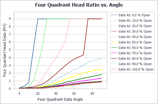
Figure 1: Typical turbine head loss data
Notice in Figure 1 that the turbine head loss data is represented by an array of curves, one for each wicket gate position. A similar array of curves is used to describe turbine net-torque (see Figure 2):
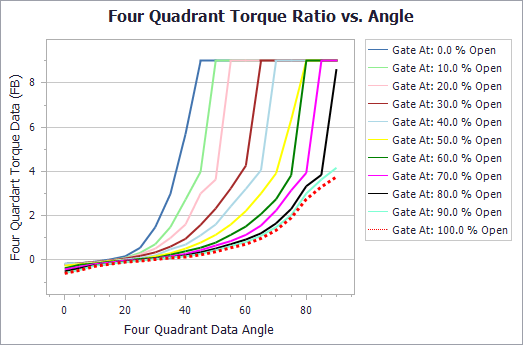
Figure 2: Turbine net-torque curve
The user must specify how many wicket gate positions are to be modeled, and how many four quadrant angles are to be modeled. With these parameters given, complete FH and FB data can be entered in the Turbine Four Quadrant Data table, as seen in Figure 3.
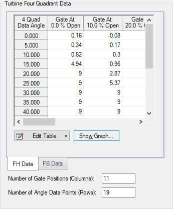
Figure 3: Sample FH data entered in the Turbine Four Quadrant Data table
The turbine four quadrant data relies on having a complete set of rated turbine performance parameters. Examples of these parameters entered in the properties window are shown in Figure 4. The importance and use of these parameters can be seen in the Turbine Waterhammer Theory help topic.
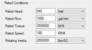
Figure 4: Sample turbine rated conditions
Turbine Transients
Generally speaking, there are three kinds of turbine transients which can be modeled in AFT Impulse.
-
Turbine Trip - Gates Initially Open, Closing During Transient Simulation
-
Turbine Startup - Gates Initially Closed, Opening During Transient Simulation
-
No Transient - Reactive Only, No Transient Gate Behavior
Turbine Trip
The turbine trip assumes the generator torque drops out instantly, between steady state and the first time step of the transient solution. Generator torque is not specified. Instead, the initial speed and four quadrant torque data provide an initial torque imbalance The initial torque imbalance is immediately resolved by an appropriate speed change (damped by inertia) when the transient simulation begins.
Turbine Startup
The turbine initial conditions may be specified as zero speed and zero flow. When this is the case, the Steady State Special Condition, in the Optional tab, must be set to “Closed”. The turbine will have zero flow in steady state, and will remain at zero flow until the gates are opened, according to the Transient Data, specified in the Transient tab. See Figure 5 for an example of this data entered in the Transient Data tab.
![]()
Figure 5: Sample input for a turbine startup
As the wicket gates open, flow and speed will increase accordingly.
No Transient
No transient data is required to simulate turbine behavior, as it reacts to circumstances. Specify only the parameters required in the Turbine Model tab. The turbine speed and flow will continuously adjust to changes in supply pressure and or discharge pressure. Keep in mind; this is essentially the same as a turbine trip, but without commanding the gates to close. The turbine speed will immediately find equilibrium with the specified initial conditions. It can be seen in the torque data that there is a crossover point, where the torque ratio goes from positive to negative. If the initial specified conditions produce an initial Theta which lies in the region of this crossover point, the turbine will be initially stable. However, if the initial torque ratio, as determined by the initial speed and flow, is NOT in the region of the crossover point, the turbine will have to resolve the non-zero net-torque with a speed change, until equilibrium is established. This speed change will occur as soon as the transient simulation begins.


