Troubleshooting Artificial Transients
It is relatively clear how an Artificial Transient is detected, but diagnosing its source and fixing the problem can be much more complicated. The tools provided by AFT Impulse can help point you in the right direction. If the methods below are insufficient, contact the AFT Support Team with your model file for further analysis.
Ensure Stability of the Steady-State Results
As with any Impulse simulation, the scenario should first be run in steady-state by selecting the Steady Only option on the Simulation Mode/Duration panel of Analysis Setup. The steady-state results are used to initialize the transient simulation; therefore, it is important that the steady-state simulation is running as expected. Any Output Messages (Critical Warnings, Warnings, or Cautions) or other convergence issues should be addressed prior to running the transient simulation.
Many Artificial Transients can be resolved by resetting the Steady Solution Control Tolerances to the Impulse defaults, or tightening both the Pressure and Flow Rate relative tolerances to 1E-6 or 1E-7.
Create a Troubleshooting Child Scenario
It is recommended to create a child scenario for troubleshooting purposes. Once the root cause and mitigation strategy of the Artificial Transient is determined, the child scenario can be deleted and the modifications can be re-applied to the original parent scenario.
By default, Impulse will halt the transient solver if an Artificial Transient is detected. We will override this behavior and allow the transient solver to continue. The following settings are useful for the troubleshooting scenario:
-
Disable the "Stop Run if Artificial Transient Detected" setting on the Artificial Transient Detection panel under the Miscellaneous group of Analysis Setup. This will allow the transient simulation to proceed despite the Artificial Transient being present.
-
Disable all user-defined transients in the model. To properly understand the Artificial Transient, it is critical that all other user-defined transients in the model are disabled (i.e., valve closures, pump trips, etc). This can be achieved by opening the Properties window of each applicable junction, going to the Transient tab, and selecting the Ignore Transient Data option. Once all transients have been disabled, the Transient Data tab in the Junctions section of the Model Data will report "Transient Special Condition set - transient data will be ignored" for each junction.
-
Save transient output data for all pipe stations by opening the Output Pipe Stations panel under the Pipe Sectioning and Output group of Analysis Setup, select all pipes by clicking the All button, and click Change Selected Pipes To All Stations. This is required for making Animated Profile Graphs that visualize the Artificial Transient moving through the pipes. For large models, you can choose to only save all stations for the pipes that were listed in the Critical Warning messages, and perhaps several surrounding pipes to minimize the run time.
-
Decrease the Stop Time to 0.2 seconds on the Simulation Mode/Duration panel under the Transient Control group of Analysis Setup. An Artificial Transient is an effect strictly related to the beginning of the simulation when the model switches from the steady-state to the transient solution methodology. When troubleshooting, it is not necessary or advised to run a long simulation. Shorten the Simulation Duration as much as possible to make running the model quick. In many cases only a handful of time steps are needed. The value of 0.2 seconds is arbitrary, but provides a balance of fast run time while still providing enough time steps to graph effectively for many models.
-
Save all output time steps by ensuring that the Save Output To File setting is set to the "Every Time Step" option on the Simulation Mode/Duration panel. This is required for making graphs that accurately depict the maximum and minimum magnitudes of the Artificial Transient.
Once the above modifications have been made, run the transient simulation which should now proceed past the Artificial Transient detection.
Look at the Output Messages
The Warnings tab may give information on the Artificial Transient(s). In Figure 1, we can see that the pressure is inconsistent at the exit of Pipes P1 and P2, and inconsistent at the inlet of Pipe P3. These 3 pipes connect to a branch junction. With this information alone, it may be possible to determine and solve the issue. The model inputs for any listed pipes and junctions should be reviewed.
In this case, the steady-state Tolerances were loosened from the default values, and the Solver was reporting about 1% error in the flow splits around this branch junction. Even though the steady-state solution was converging without errors, the tolerances were not tight enough for the transient solution methodology. The solution in this case was to revert the relative tolerances for both Pressure and Flow Rate to the default Impulse values of 1E-5.
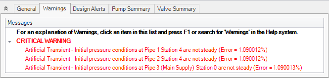
Figure 1: Artificial Transient Critical Warnings
Observe the Artificial Transients with Graph Animations
If the Output Messages do not provide enough information, then the most powerful tool for analysis of an Artificial Transient is the Animation of a Profile Graph. By animating the behavior it can be made clear where the event originates, as well as what kind of impact it has on the system. It is best to start by making graphs using the pipes listed in the Critical Warnings. It may also be useful to graph pipes near pumps, tees, branches, and control valves since there is often complex behavior occurring at these locations.
Again, user transients should be disabled which means the simulation should remain at a constant steady-state throughout the transient simulation. This makes it easy to look for any deviations from the constant steady-state which will indicate an Artificial Transient. An immediate red flag is if the Max/Min envelopes of the graph are different.
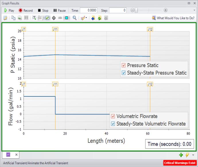
Figure 2: A profile graph showing time step zero, representing the initial steady-state solution
Advancing the animation just one time step shows a change in the pressure and flow profile:
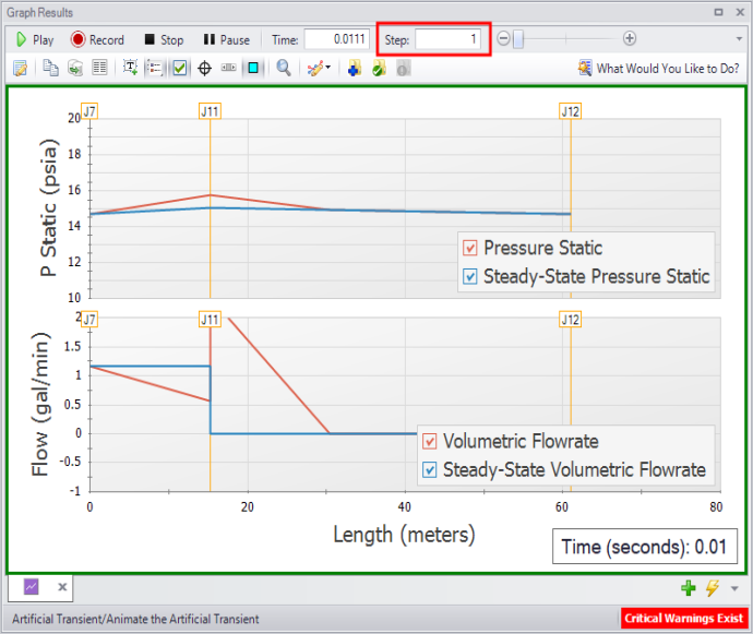
Figure 3: The same profile graph showing the Artificial Transient on the first time step
In this case, the solution was to reset the Steady Solution Control Tolerances back to the Impulse default values.
Determine the Root Cause
In some cases the error percentages listed in the Critical Warnings may be negligible, or the magnitudes of flow deviation from the steady-state in the Profile Graph Animations may be acceptable. In these cases the "Ignore Flows Less Than" setting can be adjusted on the Artificial Transient Detection panel under the Miscellaneous group of Analysis Setup. Though it should be noted that any error amount will impact the transient results, and some effort should be put into resolving the Artificial Transient without modifying this setting if possible.
In many other cases the Artificial Transient will not be negligible. In these cases the root cause of the Artificial Transient must be determined. This is often the most difficult step as there is no one potential cause. The best approach is to consider the Profile Graph Animation results as well as the engineering assumptions made by AFT Impulse and the various junctions. Check the input data for any connected pipes and junctions. Below are some example resolutions that our Support Team has seen:
-
Reset the Steady Solution Control Tolerances to the Impulse defaults
-
Tighten the Steady Solution Control Tolerances for both Pressure and Flow Rate to 1E-6 or 1E-7 (or even tighter)
-
Resolve typos in the input data such as extra zeros or incorrect unit selections
-
Prevent Air Valves from being open during the steady-state and eliminate the corresponding Warning
-
Select a different Four Quadrant Data Set which is better suited for the pump(s) used in the model
-
Switch the Tee/Wye Loss Model to Simple
-
Ensure that valve transient data has a first data point that matches the steady-state operation of the valve
Note: Do not forget to re-enable the "Stop Run if Artificial Transient Detected" setting once the troubleshooting is complete!


