Pipe Drawing Modes
AFT Impulse has a selection of pipe drawing modes. To select or change a pipe drawing mode, navigate to Arrange -> Pipe Drawing Mode. These pipe drawing modes are:
A second function called Snap to Grid is highly integrated with Pipe Drawing Modes and will alter how each pipe drawing mode works. To select or change a Snap to Grid option, navigate to Arrange -> Snap to Grid. The Snap to Grid options for the 2D modes are on and off. Snap to Grid options for Isometric are more extensive. These snap to grid options are:
-
Snap to Isometric Grid Lines
-
Snap to Grid Points
-
Do Not Snap
This Pipe Drawing Mode allows placing pipes or junctions anywhere on the Workspace, with pipes at any angle. Snap to Grid can be turned on with this mode to force the junctions to be at grid intersection points.
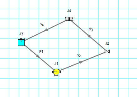
Figure 1: 2D Freeform with Snap to Grid off
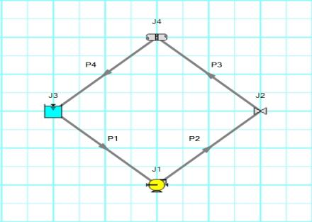
Figure 2: 2D Freeform with Snap to Grid on
The 2D Orthogonal Pipe Drawing Mode forces all pipes drawn in the model to be either horizontal or vertical. Segments are automatically inserted into pipes to enforce drawing only along the horizontal and vertical directions.
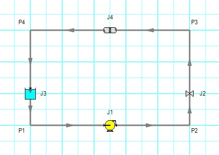
Figure 3: Model in 2D Orthogonal mode with Snap to Grid on
Orthogonal drawing can create some confusion for the user because segments from different pipes may overlap each other and hence become indistinguishable.
-
Use the Add/Remove Segments button to add new segments
-
Use a fine grid and the Snap to Grid features
-
If you have a junction with several connecting pipes that interfere, enlarge the junction to 150% or 200% of normal size using the Workspace Layers
When modeling, it may be convenient or desirable to demonstrate the three dimensional nature of a system. A typical 2D grid has two sets of grid lines representing the x and y axes. An isometric grid has three sets of grid lines that are offset by 60°, representing the x, y, and z axes. It is ideal to set the grid type desired before building a model to avoid the pipe and junction locations from being rearranged in undesired ways. It is also very helpful to show the Grid (Arrange -> Show Grid) when building an isometric model.
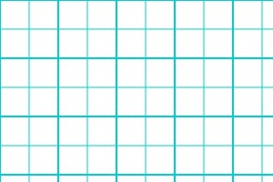
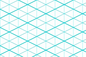
Figure 4: 2D (left) and isometric (right) grids
Drawing Pipes in Isometric Mode
How pipe drawing in isometric mode functions will change depending on the selected snap to grid option. When Snap to Isometric Grid Lines is selected, the pipes are automatically segmented to lie on the grid lines as shown below. Dragging one of the handles on the pipe shows a preview line of where the pipe will be placed if adjustment needs to be made. The placement of the preview line can be cycled through all possibilities by pressing the arrow keys or by scrolling the mouse scroll wheel. Holding the alt key while dragging a pipe endpoint will automatically add a new segment to the pipe - the placement of the line can be controlled with the arrow keys or scroll wheel as before.
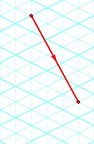
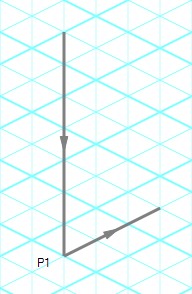
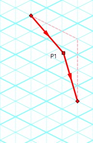
Figure 5: Automatic layout of isometric pipes
The Snap to Grid Points option will force the end points of the pipes to snap to the points where the grid lines intersect without adding segments to it. This is akin to the 2D Freeform mode while Snap to Grid is on.
The Do Not Snap option will allow the end points of the pipes to placed anywhere within the Workspace.
Placing Junctions
Placing junctions onto the Workspace follows the usual rules; however, the visual appearance of the icon is more complex than in an orthogonal grid. When icons are added after pipes are placed, AFT Impulse will rotate the icon automatically following the Workspace arrangement. When pipes are connected to icons already placed on the Workspace, right-click and select Auto-rotate Icon to adjust the icon. For manual control of icon appearance, right-click the junction and select Customize Icon to choose the desired appearance.
Note: The Rotate button in the Customize Icon window can be used to find the appropriate icon orientation.
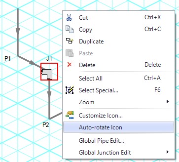
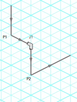
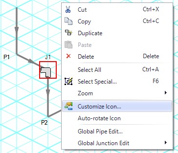
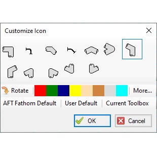
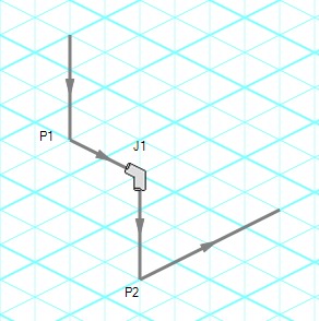
Figure 6: Icon rotations in isometric space


