Air Distribution, Multiple Design Cases - ANS (English Units)
Air Distribution, Multiple Design Cases - ANS (Metric Units)
Summary
Some system designs have multiple operating conditions to satisfy. For instance, the air distribution system discussed in the previous example may have a requirement that it operate with one of the discharge valves closed. This can be modeled in the ANS module by taking advantage of its ability to model multiple systems concurrently.
Note: This example can only be run if you have a license for the ANS module.
Topics Covered
-
Using Dependent Design Cases
-
Using Duplicate Special to create Dependent Designs
-
Understanding fractional compressor costs with Dependent Design Cases
-
Specifying Multiple Dependent Design Cases
Required Knowledge
This example assumes the user has already worked through the Beginner: Air Heating System example, or has a level of knowledge consistent with that topic. You can also watch the AFT Arrow
In addition, it is assumed that the user has worked through the Beginner: Three Tank Steam System - ANS example, and is familiar with the basics of ANS analysis.
This example is an addendum to the Concurrently Sizing a Compressor and System - ANS example, but can be worked separately from the example.
Model Files
This example uses the following files, which are installed in the Examples folder as part of the AFT Arrow installation:
-
Air Distribution.dat - engineering library
-
Air Distribution Costs.cst - cost library for Air Distribution.dat
-
Steel - ANSI Pipe Cost.cst - cost library for Steel - ANSI pipes
Step 1. Start AFT Arrow
From the Start Menu choose the AFT Arrow 9 folder and select AFT Arrow 9.
To ensure that your results are the same as those presented in this documentation, this example should be run using all default AFT Arrow settings, unless you are specifically instructed to do otherwise.
Open the US - Air Distribution - ANS Initial.aro example file listed above, which is located in the Examples folder in the AFT Arrow application folder. Save the file to a different folder. Complete the steps in the example Concurrently Sizing a Compressor and System - ANS until the Life Cycle Cost scenario is completed. Clone this scenario and name it Dependent Design Case.
Alternatively, open the US - Air Distribution - ANS Final.aro example file. Right-click the Life Cycle Cost scenario and select Save Scenario to File Without Children. Save the scenario to a new location then open this new model file. Create a child from the base scenario and name it Dependent Design Case.
Step 2. Define the Pipes and Junctions Group
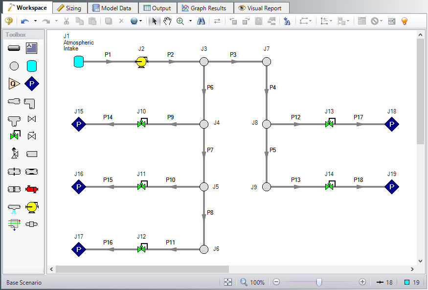
The Workspace should appear as shown in the figure below.
Step 3. Enable Dependent Design
When modeling multiple design cases, the different cases need to be broken up into a primary design case, of which there is one, and dependent design cases, of which there can be any number.
The primary design case can be any of the design cases that are being addressed in your model. Typically, it will represent the primary operating condition of the pipe system. The dependent design cases represent the same physical operating system but are used to represent differing operating conditions. If it is not clear which case should be the primary case, just pick any of the cases and call that the primary one. Design cases other than the primary case are referred to as dependent design cases. The reason why we choose a primary case and refer to the other cases as dependent cases will become clearer as we progress through this topic.
For this example, the primary design case is the system running with all discharge valves open. We want to also consider the case where one discharge is closed. The one discharge closed case will be created as a dependent design case.
To start creating the dependent design case, we will first need to enable the Dependent Design Case modeling:
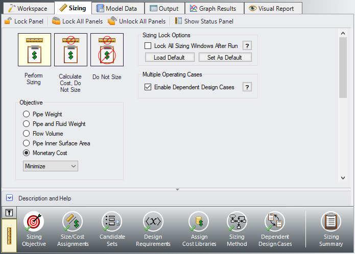
ØGo to the Sizing Objective panel and select the Enable Dependent Design Cases option. A new button will now be available for the Dependent Design Cases panel in the Sizing Navigation Panel, as can be seen in Figure 2.
Step 4. Set up the Dependent Design Case
A. Use Duplicate Special
The easiest way to set up a dependent design case is to use Duplicate Special, which will allow us to make an exact duplicate of the model in order to set up the additional operating cases. Note that you should fully define the model and all of the sizing settings for the primary case before creating the dependent cases, as has been done in this model.
To create the dependent design case:
-
Make sure that the scenario where the dependent cases will be created is loaded. In this case, you should have the Dependent Design Case scenario loaded.
-
Go to the Workspace window.
-
Choose Select All from the Edit menu, or use CTRL+A.
-
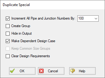
Choose Duplicate Special from the Edit menu (see Figure 3).
-
Choose an increment for the pipe and junction numbers. The number should be large enough to avoid conflicts with numbers used for other pipes and junctions in this and all other scenarios. In this case use 100.
-
Select the Make Dependent Design Case check box.
-
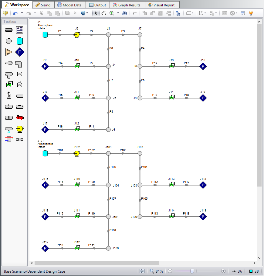
Click OK and move the duplicated version of the primary design case to an open area in the Workspace. The model should now appear similar to Figure 4.
Note that Duplicate Special also allows you to do the following:
-
Create a group for the dependent design case. This can simplify managing the pipe and junction objects in the design case.
-
Hide the pipe and junction in the output. You may want to do this for reasons to be discussed later in this topic.
-
Keep Common Size Groups. This feature is useful when using Duplicate Special for reasons other than dependent case creation, and can't be used when making a dependent design case.
-
Clear the Design Requirements. For reasons to be discussed, frequently dependent design cases will employ different design requirements than the primary design case. This option allows you to clear all the current requirements, so new ones can be assigned.
B. Apply the Dependent Design Requirements
The dependent design case capability takes advantage of the ANS module's ability to run multiple models in the same Workspace. The pipes and junctions in Figure 4 that are numbered greater than 100 (i.e., the dependent design case) represent the same pipes and junctions as those numbered less than 100 (i.e., the primary design case). It is therefore critically important that only certain data in the dependent case is changed.
Frequently the Design Requirements or Special Conditions on the pipes or junctions will be changed. However, data such as a pipe's length or compressor's performance should never change. The reason is that once this kind of data is changed, the pipe or junction is no longer the same pipe or junction, and thus the purpose of the dependent link is invalidated. The ANS module does not prevent changing data that should not be changed, but when the model is run it will check to make sure all data that should be the same actually is the same.
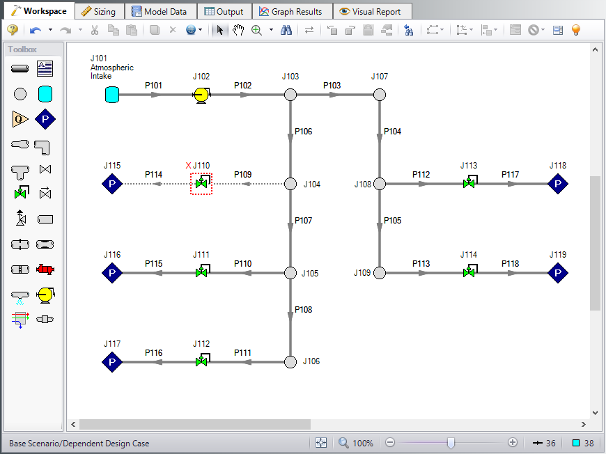
In this example we are analyzing the case where one Discharge Room in the system is shut off, so we will use Special Conditions on the discharge valve to that room.
Select Control Valve J110 in the dependent case, and use the Special Conditions button  on the Edit menu to set the junction to Closed. The dependent case should now appear as shown in Figure 5.
With one valve shutoff we will need to distribute the Fixed Mass Flow Rate of the compressor for the four Discharge Rooms remaining. That means the new Mass Flow Rate for every Control Valve will be
ØOpen the Control Valve Properties window for control valve J111 and change the flow setpoint to
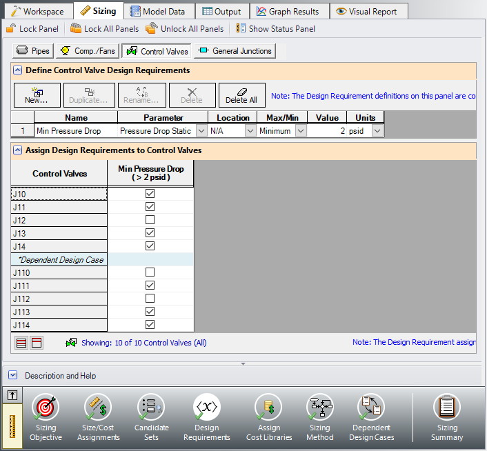
Since we have closed control valve J110 it is necessary to remove the minimum pressure drop requirement from this valve so that the results will not be skewed.
ØGo to the Design Requirements panel in the Sizing window and select the Control Valves button. Un-check the box for the pressure drop requirement next to J110 to remove it from the closed valve as shown in Figure 6.
For this scenario we also want to change the Sizing Method, since the Modified Method of Feasible Directions was determined to be the most efficient for this model.
ØClick the Sizing Method panel button in the Sizing Navigation panel, then select the Modified Method of Feasible Directions (MMFD) from the Search Method list.
The Dependent Design case is now complete, since it has inherited the rest of its sizing settings from the primary case. Select Run from the Analysis menu and got to the Output window to view the results once the run is complete.
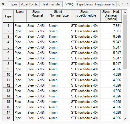
Summary
The following summary Table 1 was compiled for the two scenarios. It can be observed that when the dependent design case is included in the sizing, the cost increases by approximately 3%. With one exception, it is not possible for a model that includes a dependent design case to yield a better design than the primary case alone. At best, it can yield the same design, such as in this scenario. This is due to the fact that the dependent design case imposes additional restrictions on the solution by adding additional design requirements. If the design for the primary design case is not sufficient for the dependent design case, then the design must be changed, which will increase cost in some manner. In this case the pipe sizes needed to be increased to account for the additional load when one discharge valve is closed. The pipe sizes for the Dependent Design Case scenario can be seen in Figure 7.