Output Control
The Output Control window (see Figure 1) allows you to customize the parameters shown on the Output window. The control features are grouped on numerous tabs.
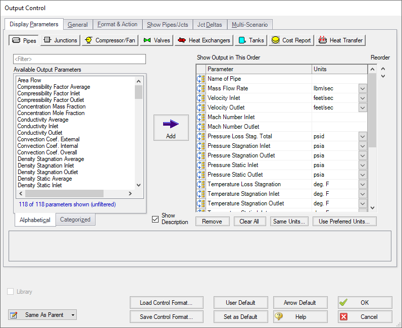
Figure 1: The Output Control window selects parameters for the Output window. Here the Pipe parameters are shown. The Junction and other parameters function the same.
Display Parameters
The Display Parameters tab controls the parameters to be shown for the pipes, junctions and summary reports. The output type is selected from the group of buttons at the top. For each output type, the list on the left side shows all available parameters for the selected report. For the pipe and junction output, this list can be viewed in alphabetized or categorized mode, which makes it easier to find a parameter. It is also possible to search the available parameters using the Filter box above the list.
Choose a parameter to be shown by selecting it on the left-hand list and clicking the Add button, or double-clicking the parameter name. The selected item will appear in the list on the right either at the bottom or at the previously selected location. The list on the right shows the order of the parameters to be displayed in the output and the units (if any) in which to display the results.
You can change the order of the output by selecting a parameter on the right-hand list, then clicking the Reorder scroll bar on the far right or by clicking and dragging the row using the handle on the left. The list will be reordered accordingly. The output is presented from left to right in the order defined in this list.
The units used for a parameter can be changed by selecting the parameter then choosing the desired units from the adjacent dropdown list. By selecting the units of interest, you can obtain your results in whatever units you find most convenient and meaningful. This means that you can enter all your input parameters in one set of units (or a variety of units, for that matter), and have all your output parameters in a completely different set of units.
To set selected units for both pipes, junctions and summary reports to the preferred units (set in the User Options window), click the Use Preferred Units button. If you change the units of a parameter and you would like that unit to be used for all similar parameters in the list or entire output, select the Same Units button.
You will note that some output parameters do not offer the ability to specify output units. These parameters either do not have units associated with them (such as Reynolds Number or friction factor), or are in fact echoes of input parameters (such as Pipe Nominal Size).
Several Special Summary Reports can be displayed in the Output window. These include the following:
-
Compressor/Fan Summary
-
Valve Summary
-
Heat Exchanger Summary
-
Tank Summary
-
Pipe Heat Transfer Output
-
Cost Report
In addition if the ANS module is active the Pipe Sizing tab will be available, as well as Design Requirements and Library tabs for each pipe/junction which has design requirements or libraries assigned to them.
General
The General Section is the text area located at the top of the Output window. The project title, reference information and solution balance display are controlled here.
You can enter a descriptive Analysis Title which will be used in the Model Data, Output and Visual Report windows. A title is required and can have up to 100 characters.
You can keep a lengthy explanation or any other documentation about your model in the Reference Information section. Names of projects, individuals, and assumptions can all be kept with the model. This information can then be included in your reports to improve tracking.
There is an option "Show Solution Balance Summary" that is defaulted to off. This option toggles the display of a general output tab showing the total flow entering and exiting each junction, as well as the sum of those flows. This can be helpful in verifying the results as well as in some troubleshooting cases.
Format & Action
The results can be automatically sent to the printer or saved to a file when the model has reached convergence. Additionally, the results can be automatically saved as initial conditions when the model is run. By saving the results, the iteration time for AFT Arrow to arrive at a converged solution is reduced. The initial guess can also be transferred manually by Selecting the Transfer Results to Initial from the Edit menu. The model can also be automatically saved after the initial conditions are transferred. The valve state (open, closed or failed) can also be saved along with the initial conditions.
When enabled, the Wrap Table Column headers option makes the output tables wrap the column headers an extra line if the header is wider than usual.
There are four formatting methods for the pipe and junction output data:
-
Always Align Decimal Point on Output - allows magnitude of the data to be easily compared as the data is read down the column. However, a number whose magnitude is small may force larger numbers to show many digits. For example, assume that the minimum number of digits is set to four, and there are two output values: 1234.5 and .09876. These two values will be displayed in the output as:
-
1234.50000
-
0.09876
-
-
Show Only Number of Digits (not aligned) - forces the data to use exactly the number of digits specified, which may result in the decimal point location changing from value to value. Using this method with the above example and four digits, the output will be displayed as:
-
1235
-
9.876E-02
-
-
Align Only When Max/Min < Limit- aligns the data on the decimal point only if the maximum value in the column divided by the minimum value is less than a limiting order of magnitude that you set. If this ratio is greater than the limit, then each value in the column will be exactly the number of digits specified. Using the above example with a limit set to 4 then 1234.5/.09876 = 12500 or an order of magnitude of 5. This is greater than the limit. The entire column will not be aligned and will be displayed as:
-
1235
-
9.876E-02
-
-
Use Exponential When Max/Min>Limit - similar to the above method except that if the ratio is greater than the limit then the entire column will be shown in exponential format. Using the above example, the column would be shown as
-
1.235E+03
-
9.876E-02
-
These formatting options are for the entire Output window; however, the last two are calculated and applied on a column basis. In other words, if you choose the third option one column may be aligned but another may not be.
The output can be forced to always display in exponential notation by choosing the checkbox.
Options to adjust the colors for the headers and design alert highlighting are also available.
Cost Report Formatting
The Cost Report monetary numerical format can be specified.
Show Pipes/Jcts
You can choose which pipes and junctions are to be displayed in the Output window. Clicking a selected item in the list on the Show Pipes/Jcts folder tab will deselect it. Clicking a deselected item will select it. This feature is especially useful when you are interested only in a certain area of the model.
You can quickly define the output you want by doing the following:
-
Select the pipes and junctions on the Workspace
-
Open the Output Control window and select the Show Pipes/Jcts tab
-
Click the Workspace button for both the pipes and junctions
-
Click the Show button
Junction Deltas
You can have AFT Arrow calculate the difference between two junctions for a particular parameter. These results are displayed in the General Section. A list of Junction Deltas is created by selecting the upstream and downstream junctions, the parameter and units of interest, then adding it to the list by clicking the Add >> button. Some parameters will require that either the inlet or outlet value for the junction be specified. The list will contain the parameter symbol and the two junction numbers with "in" or "out" in parentheses. Different parameters can be used for each item in the list so you can, for example, choose pressure difference between junctions 2 and 10 and also temperature difference between junctions 45 and 16.
Multi-Scenario
You can view output from multiple scenarios concurrently in the Output window. To do this, select the Multi-Scenario tab. This tab is only visible when at least one child scenario exists. From this tab, choose which scenarios you would like to view concurrently by clicking on the Select Scenarios button located at the bottom right of the Scenario Order and Colors box under the Multi-Scenario tab. The color of each scenario is automatically generated and can be regenerated by selecting "Reset All Colors". You can manually select the background color for the Output data of a given scenario by clicking on the ... button located in the row corresponding to the scenario.
You can also order the scenarios to appear in the Output window according to your preferences. To do this, arrange the scenarios in the order you would like them to appear by using the turquoise arrows at the bottom left corner of the Scenario Order and Colors box. Then, select how you would like the data to be displayed by clicking the appropriate choice under the Display Current Scenario section. Figure 2 shows the Output window with multiple scenarios displayed.
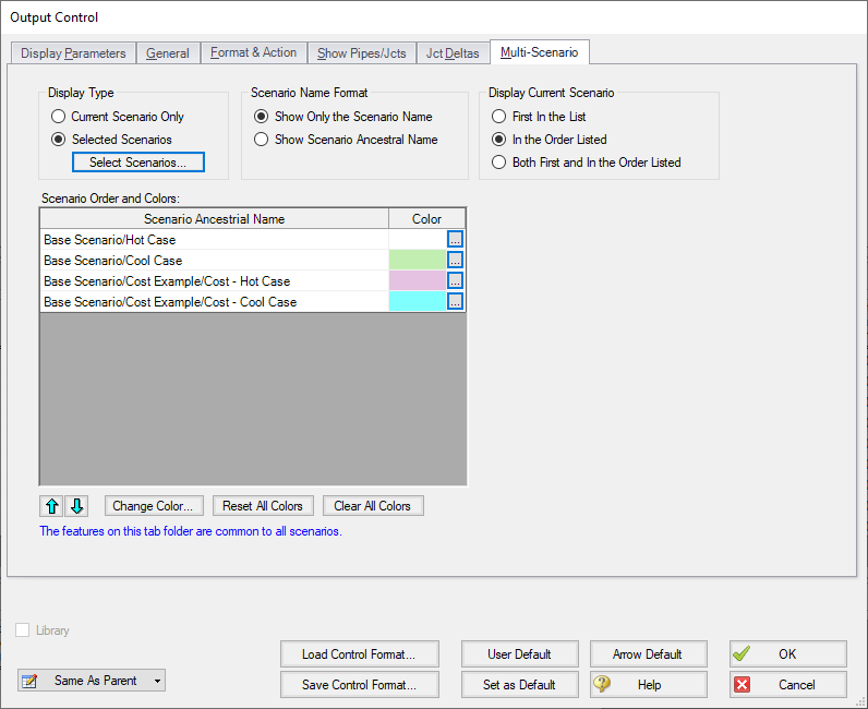
Figure 1: Output Control window selections for multi-scenario output
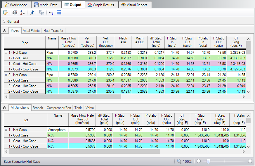
Figure 2: Output window with multiple scenarios displayed
Library Connections
In the lower left of the Output Control window there is a Library checkbox. If this box is checked, your Output Control parameters are setup as determined by the library to which you are connected. This is referred to as an active library. To make it inactive, uncheck the box or change one of the Output Control settings controlled by the library.
If the check box is unchecked, but enabled, you are connected to a library but the settings are not being passed to the Output Control window. The library is thus inactive. To make it active, check the box then click the OK button.
If the check box is disabled, there is no connected library.
Command Buttons
There are eight buttons at the bottom of the Output Control window. Arrow has built-in default parameters, units and settings which you can choose by clicking the Arrow Default button. You can also develop your own settings, tailored to your project or industry, and have these used by default (instead of Arrow’s defaults). To make your own default, first select the output parameters, units and settings you would like to use then click the Set As Default button. Your settings will be saved and will be used each time any new project is initiated. If you make changes to the settings, and want to get back to your defaults, click the User Default button. The saved settings are updated only when you click Set As Default.
You can save the output settings (except for the selected pipes/junctions and junction deltas) to a file by pressing the Save Control Format button and entering a file name. These settings are loaded again by pressing the Load Control Format button and choosing the file name. For example, you may have a final report format that is always desired. You can load this format before generating final results. If you have another format you use for reviewing model accuracy, you may want a larger number of parameters in the output.
The format files you create can be placed on a network for sharing among a group or company, allowing standardized reporting.
If you have made changes you don’t want to keep, click the Cancel button. Click OK to use the setting you have specified.
Related Topics
Use the Output Window Sort Feature
Note No Scenarios have been set in the Multi-Scenario Output display
Related Examples
Related Blogs


