Two Window Formats
Format #1: Junctions with One or Two Connecting Pipes
The first basic window format is for junction types that allow only one or two connecting pipes (see Figure 1). While junctions do not have an explicitly defined flow direction like pipes do, typically those with two pipes or less adopt a direction from the connecting pipes. For these junction types, upstream and downstream pipes are recognized by AFT Arrow based on the reference positive flow direction of the connecting pipes. The upstream and downstream pipes are displayed separately near the top of the window.
In this first basic window type, it is generally important to have the pipes' reference positive flow directions specified in the physically correct directions. A good example of this is a Compressor/Fan junction which will add pressure to the system in the direction of positive flow through the connecting pipes. The Compressor/Fan junction interprets where to add the pressure based on the directions of the connecting pipes.
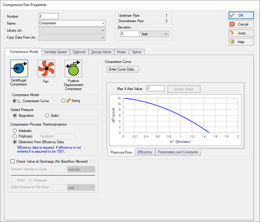
Figure 1: Properties window format #1 (fixed connecting pipe display)
Format #2: Junctions with More Than Two Connecting Pipes
The second basic window format for junction Properties windows is for junctions that allow more than two connecting pipes (see Figure 2). These junctions typically allow up to twenty-five connecting pipes; except for the Tee/Wye junction, which allows only three.
Because the number of pipes connected to a junction may vary, the second basic format uses a table sized according to the number of connecting pipes.
An example of this second window format is the Branch Properties window, shown in Figure 2, which has three connecting pipes. To determine AFT Arrow's interpretation of the model connectivity for this second window format, you can review the contents of the table areas.
K-factors in the first column will be applied for flow into the pipe and out of the junction, while K-factors in the second column will be applied for flow out of the pipe and into the junction.
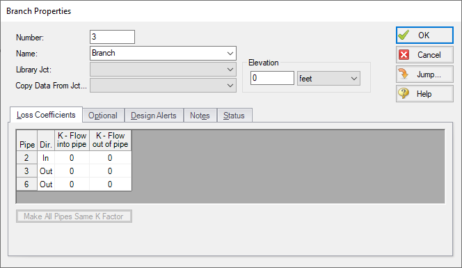
Figure 2: Properties window format #2 (pipes displayed in a table)


