Compressors & Fans
The Compressor/Fan junction allows you to model the pressure added to a system by a compressor or fan. Because all turbomachines are different, AFT Arrow does not provide any standard types. Pressure and flow data that describes the turbomachine must be obtained from the manufacturer or from test data. To reduce repeated data entry, frequently-used compressors/fans can be added to the Component library.
Common Input Information
Like all junctions, Compressor/Fan junctions require a junction number, junction name, and inlet and outlet elevations. Similar to other junctions, they can have Design Alerts and Notes applied to them. They require two connecting pipes. Note that the direction of the connected pipes defines what side of the junction is suction and which is discharge.
Compressor/Fan Model
This tab requires the selection and definition of what the junction represents. There are three models available, which are shown in Figure 1.
-
Centrifugal - Represents a typical centrifugal compressor in which a pressure rise is achieved by adding kinetic energy to the superheated gas flow. Arrow can help to size a compressor using the Sizing option. Once a compressor curve is attained, the compressor can be modeled by entering the curve into the Compressor Curve under the Compressor Model section.
-
Positive Displacement - Represents a steady state approximation of a positive displacement device. The flow is fixed to a constant value, and whatever pressure is necessary to obtain that flow will be supplied.
-
Fan - Represents a typical fan in which a large amount of gas is generally moved with a lower increase in pressure than a compressor. As with the centrifugal compressor, Arrow can help to size a fan using the Sizing option. Once a fan curve is attained, the fan can be modeled by entering the curve into the Fan Curve under the Fan Model section. The Fan model will always be treated as adiabatic. For non-adiabatic behavior the centrifugal compressor option should be chosen.
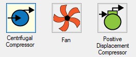
Figure 1: Compressor/Fan junction available models
Variable Speed
This tab allows the speed of the turbomachine to vary either by a fixed amount, or dynamically. These options are only available when a compressor or fan is specified with a curve.
-
Fixed Speed (%) - Directly modifies the fan or compressor curve according to the Affinity Laws. The entered curve is always assumed to be the 100% speed curve.
-
Controlled Compressor/Fan (Variable Speed) - Dynamically change the speed of the turbomachine to meet a specified control setpoint. Instead of allowing the flow or pressure to vary with a fixed speed, the speed of the compressor/fan (and thus Compressor/Fan Curve, according to the Affinity Laws) varies to meet a fixed flow or pressure. If modeling a suction or discharge pressure, control can optionally be enforced only if the value is above/below the setpoint.
Compression Process Thermodynamics
Depending on the compression process, significant thermal effects can occur. Fans create a pressure rise that is typically so low that the temperature is not noticeably affected, and this is why the fan will always be treated as adiabatic in Arrow. The large pressure rise in compressors, however, leads to significant temperature changes. See the Centrifugal Compressor topic for details on the available methods for calculating this.
Optional
There are several optional parameters that can be defined for a compressor/fan. Some of these are available to most junctions such as Initial Guesses, Display on Workspace, Design Factor, and Workspace Icon.
Also present are several compressor/fan junction specific options:
-
Special Condition
-
None - The compressor/fan operates normally.
-
Compressor/Fan Off No Flow - The compressor/fan is shut off and blocked. This is identical to a closed valve.
-
Compressor/Fan Off With Flow Through - The compressor/fan is shut off but allows flow to continue through. This is identical to a lossless connection.
-
-
Number of Compressor/Fans at This Location - Several compressor/fans can be represented by one Compressor/Fan junction. This simplifies the model by reducing the number of pipes and junctions present, as well as automatically calculating the resulting composite Compressor/Fan curve. When this option is selected the compressor summary will show the total flow/pressure added from the combined compressors/fans.
-
Additional Efficiency Data - Power and efficiency information for each stage in a VFD-Motor-Compressor/Fan assembly.
Related Topics
Compressor/Fan Efficiency Data
Compression Ratio Reference Inlet Conditions
Positive Displacement Compressor
Junction X Had Reverse Flow - Compressor/Fan Pressure Could Not Be Predicted
Junction X Exceeded Runout Flow Rate…
Junction X Compressor/Fan Added Negative Pressure
Poor Compressor/Fan Curve Fits
Related Examples
Related Blogs


