Variables Panel
(GSC Module Only) The Variables panel is where variables are defined and applied for use with the GSC module (Figure 1). Variables are input parameters that the GSC module will change to achieve the user's desired goals. Generally, there must be one variable applied for each goal that is applied.
Types of Variables
All variables are junction parameters. The variables that are available for each junction type are shown in Table 1. There are over 30 types of variables.
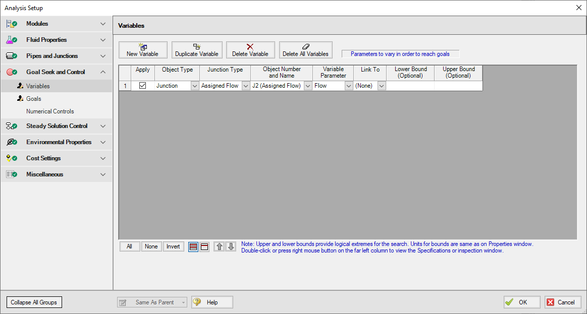
Figure 1: GSC Variables are input parameters to be automatically varied
Types of Variables
All variables are junction or pipe parameters. The variables that are available for each object type are shown in Table 1. There are over 30 types of variables.
Table 1: List of object types with available variables
| Object Type | Variables | Restrictions |
| Pipes |
Design Factor Friction ID Reduction (Scaling) Insulation Thickness |
|
| Assigned Flow |
Flow Temperature |
|
| Assigned Pressure |
Pressure Temperature |
|
| Branch | Imposed Flow | |
| Check Valve |
Loss Value CdA |
|
| Compressor/Fan |
Speed Flow Head Rise Impeller Size Pressure Rise |
|
| Control Valve | Control Setpoint | |
| General Component |
Loss Factor CdA |
|
| Heat Exchanger |
Loss Factor Heat Rate Discharge Temperature Temperature Rise Enthalpy Rise Heat Transfer Area Overall Heat Transfer Coefficient Secondary Flow Secondary Inlet Temperature |
|
| Orifice |
Diameter/Area Loss Factor CdA CdA Sonic/Subsonic |
|
| Relief Valve |
Loss Value CdA |
|
| Screen |
Open Area Loss Factor CdA |
|
| Spray Discharge |
Spray Area Number Sparger Holes CdA |
Only for Sparger
|
| Tank |
Pressure Temperature |
|
| Valve |
Loss Value CdA Open Percent |
Creating and Deleting Variables
To create a variable, click the New Variable button on the Variables panel (Figure 1). This will insert a new item into the variable list. After the variable has been added, the variable data is defined by entering the necessary data in each of the data columns.
Variables may also be added by duplicating an existing variable, then modifying the data for the new variable. To duplicate a variable, select the variable to be duplicated from the variable list, and click the Duplicate Variable button.
To delete a variable, select the variable by clicking on the appropriate row in the variable list. After selecting the variable to be deleted, click the Delete Variable button. If you want to delete all of the variables in the list, click the Delete All Variables button.
Defining Variables
For each variable the following settings can be defined:
-
Object type - The Object Type defines whether the variable applies to a pipe or a junction.
-
Junction type - The Junction Type column is used to define the type of junction to which the variable is being applied.
-
Object number and name - The specific junction to vary is selected in the Junction Number and Name column. The list will only display junctions of the type selected in the Junction Type column.
-
Variable parameter - Each junction type has a specific set of parameters that are available as variables (Table 1). The list will only display parameters that are available for the junction type selected in the Junction Type column.
-
Linking variables - The Link To column is used to force a variable on multiple junctions of the same type to solve to the same value.
-
Variable bounds - During a goal search, the GSC module will modify the values for the defined variables. Sometimes it is helpful to specify upper and lower bounds for variables to provide logical extremes during the goal search. Some examples of logical bounds that can be applied would be lower and upper bounds on valve open percentage of 0% and 100%, respectively.
An example where this would be desirable would be when using flow setpoint as a variable for several control valves in parallel. It is often desirable to solve for a condition where the setpoint is the same for all of the valves. This can be accomplished by using variable linking. A setpoint variable would be defined for each of the control valves. Then, one of the control valves would be selected as the basis object, which just means no linking is specified for this control valve. The other control valves would be linked to the basis object by selecting the basis control valve from the list in the Link To column.
Note that bounds can have engineering units, but these units are not displayed. It is assumed the units are the same as the junction input parameter Properties Window.
Organizing Content
The lower left corner of the panel features options for rearranging and selecting variables and goals. All will select all available variable or goals. None will deselect all variables or goals. Invert will invert which variables and goals are selected. There are also options to show all variables or goals and to show only the applied variables or goals. The goals and variables can also be reordered using the turquoise arrows to change their position.
The Same As Parent button allows the variables, goals, numerical control, or all of the parameters (in regards to the Goal Seek and Control Group) of the parent scenario to be copied down to the child scenario.
Reviewing Pipe/Junction Data
Data for the selected objects in the Variables panel can be reviewed and edited without having to close the Analysis Setup window.
-
Reviewing object input data - If you would like to see the input data for the junction selected as a variable, press the right mouse button on the far left column in the Variables table. The inspection window will display, showing you the input data.
-
Editing object input data - Similar to the inspection feature just described, you can open the Pipe or Junction Properties window by double-clicking the far left column in the Variables table. From there you can change any data desired.
Applying Variables
Once a variable has been created, the user must specify if a variable is to be used when the GSC module is run. To apply a variable, select the checkbox in the Apply column.
Using the Apply feature allows the user to define multiple variables that can be used in alternate cases or analyses. Any of the variables that are not being used for a particular analysis can remain in the list for later use. Click the Apply checkbox for the variables that are to be used in the current analysis.


