Cooling System - GSC (English Units)
Cooling System - GSC (Metric Units)
Summary
The objective of this example is to use the GSC module to vary the required pump speed and control pressure such that a minimum flow of
Note: This example can only be run if you have a license for the GSC module.
Topics Covered
-
Applying multiple variables and goals.
-
Using linked variables
Required Knowledge
This example assumes the user has already worked through the Walk-Through Examples section, and has a level of knowledge consistent with the topics covered there. If this is not the case, please review the Walk-Through Examples, beginning with the Beginner: Three Reservoir Model example. You can also watch the AFT Fathom Quick Start Video Tutorial Series on the AFT website, as it covers the majority of the topics discussed in the Three-Reservoir Model example.
In addition the user should have worked through the Beginner: Heat Transfer in a Pipe - GSC example.
Model Files
This example uses the following files, which are installed in the Examples folder as part of the AFT Fathom installation:
Step 1. Start AFT Fathom
From the Start Menu choose the AFT Fathom 12 folder and select AFT Fathom 12.
To ensure that your results are the same as those presented in this documentation, this example should be run using all default AFT Fathom settings, unless you are specifically instructed to do otherwise.
Step 2. Open the Model
Open the
Load the Pump A scenario and turn off Pump J5 by opening the properties window, navigating to the Optional tab, and selecting the Pump Off No Flow special condition.
Open the properties window for Control Valves J11. On the Control Valve Model tab, under Loss When Fully Open, select Cv and then select From Open % Table (on Optional Tab) for the Loss Source. Go to the Optional tab and add the following data to Open Percentage Data table:
| Open Pct. | Cv |
|---|---|
| 0 | 0 |
| 100 | 150 |
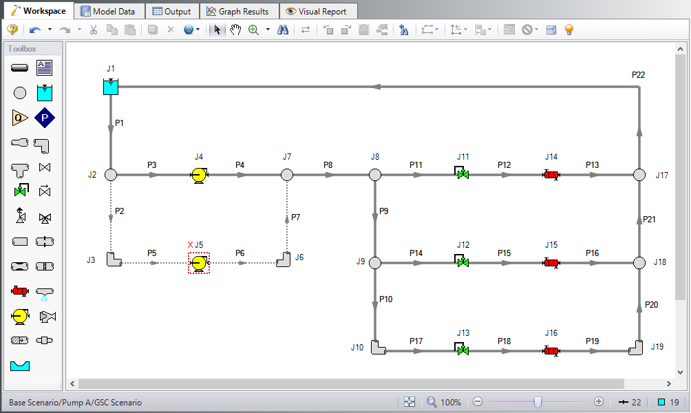
Click OK. Make these same changes to Control Valves J12 and J13. The workspace should look like Figure 1 below:
Step 3. Define the Modules Group
Open Analysis Setup, which should bring you to the Modules panel. Check the box next to Activate GSC. The Use option should automatically be selected, making GSC enabled for use.
Step 4. Define the Goal Seek and Control Group
Specify the variables and goals for the model.
Variables Panel
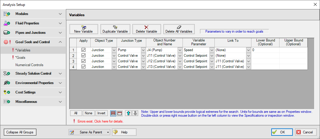
Open the Variables panel in the Goal Seek and Control group in Analysis Setup. For this example, we will be adding four variables: one pump variable and three control valve variables which will be linked. Enter the variable inputs shown in Figure 2:
Goals Panel
There should be one goal defined for each variable. In this case we essentially have two variables, since all of the control valve variables are linked, causing them to act as a single variable.
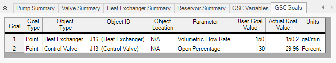
Open the Goals panel in the Goal Seek and Control group in Analysis Setup. Create two new goals as defined below in Figure 3:
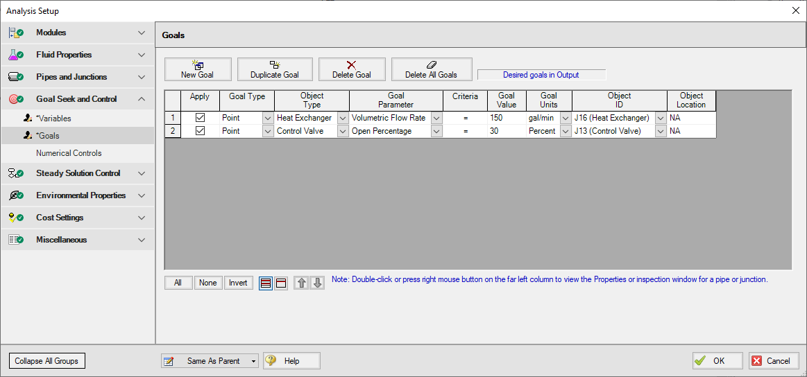
After entering the data, the Goals panel should appear as shown in Figure 3. Note that by setting the most hydraulically remote heat exchanger and control valve equal to the minimum requirements, we are ensuring that the other heat exchangers and control valves will exceed the minimum values.
Step 5. Run the Model
Click Run Model on the toolbar or from the Analysis menu. This will open the Solution Progress window. This window allows you to watch as the AFT Fathom solver converges on the answer. This model runs very quickly. Now view the results by clicking the Output button at the bottom of the Solution Progress window.
Step 6. Examine the Output
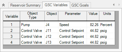
The results of the GSC module analysis are shown in the General Output section. The GSC Variables tab shows the final values for the variable parameters, as shown in Figure 4. The pump speed was determined to be
Viewing the Valve Summary tab will show that control valves J11 and J12 have open percents above the minimum of 30%. The Heat Exchanger Summary tab will similarly show that heat exchangers J14 and J15 have volumetric flow rates above the required minimum of