Hot Water System (English Units)
Hot Water System (Metric Units)
Summary
The objective of this example is to select the best pump configuration for a hot water system. The design goals of the system are:
-
Minimum
-
Maximum
-
No NPSH violations
-
All pumps must operate between 70% and 100% of BEP
-
The selected pump must also work in a special operating mode with one pump off
-
The best pump will meet all the requirements and use the least power.
Topics Covered
-
Using Junction Libraries to enter data
-
Using multiple pump configurations
-
Using NPSH and Efficiency data for pumps
-
Turning off parts of a model to simulate different operating conditions
Required Knowledge
This example assumes the user has already worked through the Beginner: Three Reservoir Problem example, or has a level of knowledge consistent with that topic. You can also watch the AFT Fathom Quick Start Video Tutorial Series on the AFT website, as it covers the majority of the topics discussed in the Three-Reservoir Problem example.
Model Files
This example uses the following files, which are installed in the Examples folder as part of the AFT Fathom installation:
-
Hot Water System.dat - engineering library
Step 1. Start AFT Fathom
From the Start Menu choose the AFT Fathom 12 folder and select AFT Fathom 12.
To ensure that your results are the same as those presented in this documentation, this example should be run using all default AFT Fathom settings, unless you are specifically instructed to do otherwise.
Step 2. Define the Fluid Properties Group
-
Open Analysis Setup from the toolbar or from the Analysis menu.
-
Open the Fluid panel then define the fluid:
-
Fluid Library = AFT Standard
-
Fluid = Water (liquid)
-
After selecting, click Add to Model
-
-
Temperature = 150 deg. F
-
Step 3. Define the Pipes and Junctions Group
At this point, the first two groups are completed in Analysis Setup. The next undefined group is the Pipes and Junctions group. To define this group, the model needs to be assembled with all pipes and junctions fully defined. Click OK to save and exit Analysis Setup then assemble the model on the workspace as shown in the figure below.
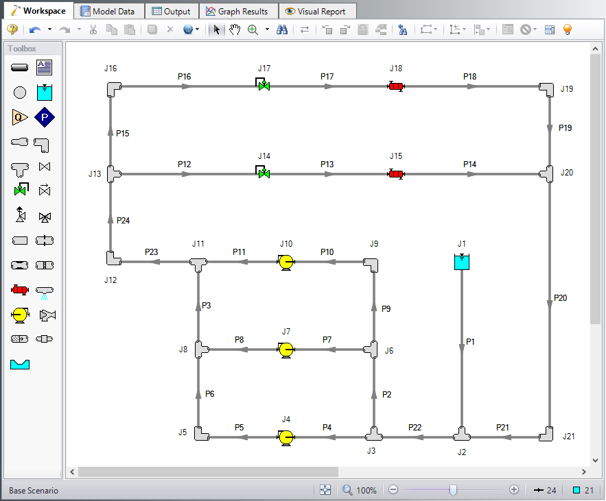
Figure 1: Model Layout for Hot Water System
Note: A safety factor of 10% will be added to all pipe and junction friction losses. This is added by typing in 1.1 in the Pipe Friction field for Design Factors found on the Optional tab in the Pipe Properties window. The Design Factor of 1.1 will be added to the Junction Friction Losses on the Optional tab in the Junction Properties windows for every junction except for the three pumps.
Pipe Properties
-
Pipe Model tab
-
Pipe Material = Steel - ANSI
-
Pipe Geometry = Cylindrical Pipe
-
Size = Use table below
-
Type = STD (schedule 40)
-
Friction Model Data Set = Standard
-
Lengths = Use table below
-
| Pipe | Size | Length (feet) |
|---|---|---|
| 6, 9 | 4 inch | 30 |
| 5, 8, 11, 13, 15, 17, 19 | 4 inch | 50 |
| 4, 7, 10, 12, 16 | 4 inch | 100 |
| 14, 18 | 4 inch | 150 |
| 2, 3 | 6 inch | 30 |
| 21, 23 | 6 inch | 50 |
| 1, 22, 24 | 6 inch | 100 |
| 20 | 6 inch | 300 |
-
Optional tab
-
Design Factors
-
Pipe Friction = 1.1
-
-
Junction Properties
-
J1 Reservoir
-
Name = Topping Tank
-
Liquid Surface Elevation = 10 feet
-
Liquid Surface Pressure = 0 psig
-
Pipe Depth = 10 feet
-
-
All Tees
-
Elevation = 0 feet
-
Loss Model = Simple
-
-
All Bends
-
Inlet Elevation = 0 feet
-
Type = Standard Elbow (knee, threaded)
-
Angle = 90 Degrees
-
-
J14 & J17 Control Valves
-
J14 Name = FCV A
-
J17 Name = FCV B
-
Inlet Elevation = 0 feet
-
Valve Type = Flow Control (FCV)
-
Control Setpoint = Volumetric
-
Flow Setpoint = 220 gal/min
-
-
All Pumps & Heat Exchangers
-
J4 Name = Pump A
-
J7 Name = Pump B
-
J10 Name = Pump C
-
J15 Name = HX A
-
J18 Name = HX B
-
Inlet Elevation = 0 feet
-
To enter the pump and heat exchanger data, we will use a pre-defined library:
-
Open the Library menu and select the Library Manager.
-
At the bottom, click Add Existing Library. Navigate to the AFT Fathom 12 Examples folder and select the file titled Hot Water System.dat and Open. The library Hot Water System will be added to the list of available libraries.
Note: Typically when a Library is first added to the list in Library Manager, it will automatically be connected and will appear with a checkmark next to it. step 3 below is only needed if the library is not automatically connected.
-
If not already, check the box next to the library name Hot Water System, this will connect the library to the model.
-
Close Library Manager
-
Now open the Pump Properties window for Pump A, and in the Library Jct field at the top of the properties window, select
-
In the Pump Curve area, make sure RPM = 1800 RPM and Impeller = 6 inches.
-
Repeat this process for Pump B and Pump C.
-
Open the Heat Exchanger Properties Window for HX A, and select
-
Repeat these steps for HX B.
Finally, use Global Junction Edit to add the 10% safety factor.
-
Select Global Edit then Global Junction Edit from either the toolbar or Edit menu.
-
Select Common Data
-
Click Select Common Junction Data
-
In the Design Factor area, set Junction Friction Loss = 1.1
-
Click OK
-
Click All to select all junctions in the list
-
Check the box in the Parameters to Change (Select in List) area next to Design Factor 1.1
-
Click Apply. A message should appear to inform you that changes were successively applied.
-
Click OK.
ØTurn on Show Object Status from the View menu to verify if all data is entered. If so, the Pipes and Junctions group in Analysis Setup will have a check mark. If not, the uncompleted pipes or junctions will have their number shown in red. If this happens, go back to the uncompleted pipes or junctions and enter the missing data.
Step 4. Run the Model
Click Run Model on the toolbar or from the Analysis menu. This will open the Solution Progress window. This window allows you to watch as the AFT Fathom solver converges on the answer. This model runs very quickly. Now view the results by clicking the Output button at the bottom of the Solution Progress window.
Step 5. Examine the Output
After running the model, select the Pump Summary tab and review these results. The pump summary data is shown in Figure 2.
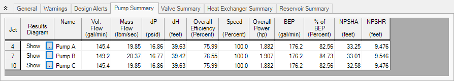
Now we must review these results to determine if the requirements are met. The pumps operate at
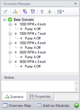
After examining this pump configuration, this process needs to be repeated for each configuration, in order to find which pump best meets the specified requirements. A tool that can be used for this kind of evaluation is the Scenario Manager. Open the Scenario Manager on the Quick Access Panel and create five scenarios, one for each pump configuration. Below each scenario, create a child scenario for each configuration named Pump A Off. The Scenario Manager on the Quick Access Panel should look like Figure 5. Alternatively, you can access the Scenario Manager from the Tools menu.
Now, work your way through each scenario and change the pump configuration to the pump configuration for each scenario. Run each scenario, note the sum of the three pump's power usage, and determine if the pump meets all the requirements. It would help to create a table of the requirements and configurations as shown in Table 1.
Table 1: Summary Table for Hot Water System
| Pump | 1800 x 6 | 1800 x 7 | 1800 x 8 | 3600 x 4 | 3600 x 5 |
|---|---|---|---|---|---|
| Normal Mode | |||||
| BEP OK? | Yes | Yes | No | No | No |
| NPSH OK? | Yes | Yes | Yes | Yes | Yes |
| FCV dP OK? | No | Yes | Yes | Yes | Yes |
| Pipe Velocity OK? | Yes | Yes | Yes | Yes | Yes |
| Power Used (hp) | 5.671 | 8.401 | 11.948 | 11.948 | 21.899 |
| Special Mode | |||||
| NSPH OK? | Yes | Yes | Yes | Yes | Yes |
| FCV dP OK? | No | Yes | Yes | Yes | Yes |
| Pipe Velocity OK? | Yes | Yes | Yes | Yes | Yes |
From Table 1, it can be seen that the only configurations that meet all the requirements are the 1800 RPM x 7-inch impeller. One thing to note is that the 1800 RPM x 8-inch and 3600 RPM x 4-inch configurations are actually the same pump configuration due to the affinity laws. The power usage of both configurations help show that they are the same pump.
Note: The 1800 RPM x 6-inch configuration with Pump A turned off is a case where the flow control valves will have to add pressure in order to maintain their set point. A flow control valve adding pressure is physically unrealistic, however, it is useful for troubleshooting purposes because it shows how close a control valve is to being able to maintain set point. The fact that the FCVs fail with this particular scenario is an example of how a certain pump configuration and operating condition may not be able to provide the system pressure and meet the requirements.


