Model Data Window
The Model Data window offers a text-based perspective on all engineering information in the pipe flow model. This window is immensely useful for obtaining a global view of the model and rapidly checking the input.
The Model Data window does not offer any tools to build or add to a model; all model assembly must happen in the Workspace.
The Model Data window allows you to manipulate existing elements from the Workspace. Therefore, a complete model can be assembled in the Workspace window without ever opening the Model Data window. In fact, for small models this may be the preferred approach.
General, Pipe, and Junction section display sizes can be changed by the user by clicking and dragging the bars between each section to resize them. Each section can also be hidden by clicking the arrow in the upper left of each section.
You can use the zoom feature in the lower right hand corner of the Model Data window to resize the text displayed on screen.
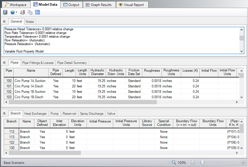
Figure 1: The Model Data window displays input in text form
Editing Features
The Pipe table allows display of all input data for all pipes in the model. Details of Fittings & Losses are displayed in the Pipe Loss Data table, accessed with an adjacent tab. The Pipe Loss Data table displays all fittings with K factors grouped into columns.
The other display tab in the pipe area is the Pipe Detail Summary, which assembles a list of details about each pipe in another format useful to some engineers.
The junction data area is below the pipe data area. Here the junction data is separated into tables for each junction type. Click the tabs to see the data for any type of junction.
To edit information in the Model Data window, you can open the Properties Window for the pipe or junction. This can be done by double-clicking anywhere in the row for the pipe or junction to be edited. Alternatively, you can use the Global Edit windows opened from the Edit menu.
-
XTS Module tables - When using the XTS Module, a Transient Data table in the Junction area displays all transient data entered for junctions. If there is no transient data, the table will not be displayed.
-
GSC Module tables - When using the GSC Module, if GSC data has been entered in the Goal Seek and Control Group in Analysis Setup, the variable and goal data will be displayed in the General section in a "Goal Seek & Control" table.
Display and Printing Features
Model Data Control lets you specify the combination of pipe, junction, and general information you want to see in the Model Data Window.
The Model Data Print Content window lets you specify the content to include in the printed Model Data report and select the font to be used for printing. This window is opened from the Tools menu (or Toolbar).
The Model Data window contents can be:
-
Copied to the clipboard
-
Saved to a formatted text file
-
Exported to a delimited file suitable for direct importing into spreadsheet software
-
Saved directly to an Adobe PDF file
-
Sent to the printer
Related Blogs


