Model Data Control
The Model Data Control allows you to customize what data to show for the pipes and for each junction type and also which pipes and junctions to show (see Figure 1). It can be opened from the Tools menu (or Toolbar).
Pipe Data Display
The data to be shown for the pipes is selected on the left side of the Model Data Control window. Only the items with check marks will be shown in the Model Data window. All pipes shown will report the selected items.
Junction Data Display
The data to be shown for the junctions is selected on the right side of the Model Data Control window. The data is grouped by junction type. However, some data is general and applied to each of the junction types. Select the junction type from the list and then select the data for that junction type. Each type also includes the general data which may be selected/deselected.
You can select/deselect the general data for all junction types simultaneously by clicking Set Common.
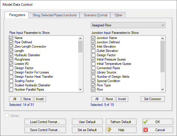
Figure 1: The Model Data Control window allows selection of the parameters to show in the Model Data window
Model Data Format
The Model Data Control format can be saved to a file so that the format can be quickly applied to other model files. There are multiple ways to do this. The Model Data Control format can be saved to the internal user library by clicking the Set As Default button, then choosing User Default in a new model file to apply the settings.
The Model Data format can also be saved to an external file, which can then be shared with different users. The external file can be generated by clicking the Save Control Format button at the bottom of the window. The format can then be applied to other model files by clicking the Load Control Format button.
Show Selected Pipes and Junctions
Specific pipes and junctions can be shown in Model Data. Click the Show Selected Pipes/Jct tab, then click the items in the lists to select the pipe(s) and junction(s) to be shown.
Other Data
When pipes with intermediate elevations are specified, you can specify which pipe data is to be displayed in the Model Data window:
-
Show only pipes with intermediate elevations
-
Show only non-horizontal pipes
-
Show all pipes
In addition, you can specify whether to show Pipe Elevation Data, whether junction curve data is to be displayed with the Model Data, whether to display Design Alerts, and whether to include a Bill of Materials.
Scenario Format
A powerful Model Data feature when using scenarios is to show all direct ancestor data in the Model Data along with data from the current scenario. The Scenario Format features allow you to do this, and to highlight where data changes occur. Note that the scenario name is appended to the pipe and junction number in the left columns. This tab only appears when multiple scenarios exist.
Library Connections
In the lower left of the Model Data Control window there is a Library checkbox. If this box is checked, your Model Data Control parameters are setup as determined by the library to which you are connected. This is referred to as an active library. To make it inactive, uncheck the box or change one of the Model Data Control settings controlled by the library.
If the check box is unchecked, but enabled, you are connected to a library but the settings are not being passed to the Model Data Control window. The library is thus inactive. To make it active, check the box then click the OK button.
If the check box is disabled, there is no connected library.


