Orifice Loss Model
Sharp-Edged Orifice with Identical Upstream and Downstream Diameters
The orifice loss factors are all for turbulent Reynolds numbers. The sharp-edged orifice shown in Figure 1, is given by the following (IdelchikIdelchik, I. E., Handbook of Hydraulic Resistance, 4th edition, Begell House, Redding, CT, 2007. 2007, 259):

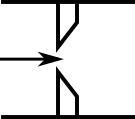
Figure 1: Sharp-edged orifice (in this case Aup = Adown)
Round-Edged Orifice with Different Upstream and Downstream Diameters
When the upstream and downstream pipe diameters are different for a round-edged orifice as shown in Figure 2, the round-edged orifice equation for different pipe areas is used and is given by the following (Idelchik 2007, 258)

where

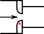
Figure 2: Round-edged orifice with different upstream and downstream pipe areas
Round-Edged Orifice with Identical Upstream and Downstream Diameters
When the upstream and downstream pipe diameters are the same for a round-edged orifice as shown in Figure 3, the round-edged orifice equation for the same pipe areas is used and is given by the following (Idelchik 2007, 262)

where

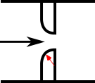
Figure 3: Round-edged orifice with the same upstream and downstream pipe areas
For other orifice configurations, see Chapter 4 of Idelchik's Handbook of Hydraulic Resistance (2007).
Orifice Discharge Coefficient
The relationship between orifice CD and K is given by Crane A-20Crane Co., Flow of Fluids Through Valves, Fittings, and Pipe, Technical Paper No. 410, Crane Co., Joliet, IL, 1988.:

where β is the diameter ratio of the orifice diameter to the upstream pipe diameter, or


