Defining Forces
AFT Impulse includes the ability to calculate dynamic, unbalanced hydraulic forces. These unbalanced forces occur when a transient pressure wave passes through a portion of the system.
Note: As AFT Impulse is only a hydraulic solver, only hydraulic forces are accounted for. AFT Impulse is not a pipe stress analyzer and as such does not have the ability to directly model piping supports or similar objects. Hydraulic force files can be generated for import into software designed for force analysis.
Defining Force Sets
In order to process force data, the locations where the forces are to be calculated must be defined. Force Sets can be defined either from the Workspace or from the Force Definitions panel of the Forces group in Analysis Setup.
Defining from Analysis Setup
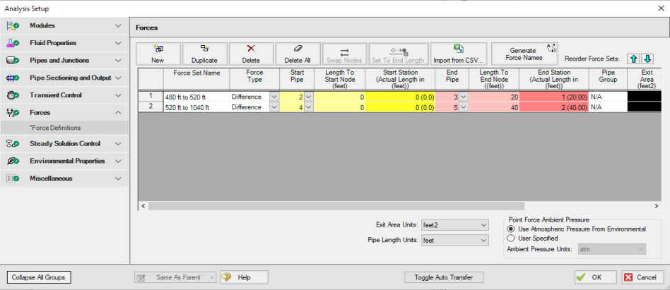
Figure 1: Force set data is defined on the Forces panel in the Analysis Setup window
-
New - Add a new force set to the table
-
Duplicate - Copy an existing force set
-
Delete/Delete All - Remove force sets
-
Swap Nodes - The calculation will be the same, but the sign of the force will be reversed. This may be important for proper interpretation of results or for exporting data to other applications.
-
Set To End Length - Automatically set the selected length field to the pipe length
-
Import from CSV - If force sets are defined in another application or by hand they can easily be imported with a comma separated value file. Click the Import from CSV button for an explanation on the required format.
-
Generate Force Names - Automatically changes the names for the selected force sets to "upstream junction name - downstream junction name" using the names from the connected junctions on the workspace.
-
Point Force Ambient Pressure - If using a Point force set, the ambient pressure is required to calculate the force balance. This defaults to the Environmental Properties panel value, but can be changed here.
Each individual force set has a number of required parameters:
-
Force Type - There are several force set types available. They are described in detail in Force Set Types.
-
Force Set Name - A unique name for the force set.
-
Start Pipe - Where the first (only for Point type) node is located.
-
Length To Start Node - The length from the beginning of the pipe to where the force set starts.
-
Start Station (Actual Length) - Because calculations must be performed at calculation stations (nodes), the exact length entered in the previous field may not be a valid calculation point. In this case, the nearest valid node will automatically be determined and displayed here. Keep in mind that the actual force set is between the two "Actual Length" fields, and can be different than the entered values.
-
End Pipe - The second (for difference types) node. Note that the selection must be valid for the specified force type. See Force Set Types.
-
Length To End Node - The length from the start of the pipe to the end node.
-
End Station (Actual Length) - As described above, the nearest calculation station to the entered length.
-
Pipe Group - For force sets across 3+ pipes, a group is required and is selected here.
-
Exit Area - For Exit type forces, an exit area is required.
-
Force Unit Vector Coordinates - Define unit vectors for your linear pipe to give the resulting forces a three-dimensional direction. Impulse is still only a one-dimensional fluid modeling software, and specifying a unit vector will not change the force calculations. However, by defining the XYZ vector for a given force set, that data can be brought into other software for further analysis using the Export Force Data tool. These unit vectors should be defined based on the coordinate system in the force stress analyzing software that the force sets will be exported to.
Defining from the Workspace
Force Sets for individual pipes can be defined directly from the workspace by right-clicking on a selected pipe. Choose the Create Force Set With Selected Pipe... option to launch the Create Force Set window, shown below in Figure 2. If multiple pipes are selected, an individual Difference Force Set will be created for each pipe applying the specified settings for each.
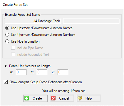
Figure 2: Create Force Set window in the Workspace
Each force has several of required and optional parameters:
-
Pipe Name - If the pipe has a name entered other than 'Pipe', the user can choose whether to include that pipe name or not in the Force Set name.
-
Force Set Name - Users can add a name for the Force Set to better organize and manage Force Sets in the model.
-
Force Unit Vectors or Length - Define unit vectors for your linear pipe to give the resulting forces a three-dimensional direction. Impulse still only a one-dimensional fluid modeling software, and specifying a unit vector will not change the force calculations. However, by defining the XYZ vector for a given force set, that data can be brought into other software for further analysis using the Export Force Data tool. These unit vectors should be defined based on the coordinate system in the force stress analyzing software that the force sets will be exported to.
-
Show Force Definitions panel after Creation - If checked the user will be brought to the Force Definitions panel to view all Force Set information defined for that scenario.
Related Blogs
Q&A: Calculating Transient Forces for Pipe Stress Analysis
Five Fantastic New Features for Fast Fluid Transients: Impulse 8


