Force Theory
The force features in AFT Impulse are intended to calculate the imbalanced hydraulic loading on a series of pipes rather than the total forces on those same pipes. Thus, most systems will see steady state forces calculated as zero. However, systems such as an exit nozzle will see a non-zero steady state force, since there is a hydraulic force imbalance across that valve even at a steady flow rate.
It is also important to keep in mind that AFT Impulse is not a tool built for the analysis of pipe stress. In real systems, the configuration and location of supports, the deflection of pipes and components, and other effects of dynamic loading should be considered. All piping and components in AFT Impulse are considered to be completely fixed in time and space, unless directed to change in a specified way, such as a valve closure. The forces that can be calculated by a hydraulic solver such as AFT Impulse are only imbalanced hydraulic forces - not forces or stresses in pipe walls or supports.
Considering the above, the calculations for forces proceed under the following assumptions:
-
All piping and components are assumed to be completely rigid. No deflections or deformations are considered.
-
The force due to gravity is neglected.
-
The volume of any junctions (bends, valves, etc.) is considered negligible. This is consistent with how junctions are modeled throughout AFT Impulse.
-
All Difference Force sets comprise a pipe or set of pipes that are axially aligned between the beginning or ending nodes.
-
Friction effects are modeled using the steady-state Darcy-Weisbach equation throughout the entire simulation.
-
The total force acting on the piping is assumed to be equal and opposite to the forces acting on the fluid.
A complementary resource to this discussion is an AFT whitepaper titled Evaluating Dynamic Loads in Piping Systems Caused by Waterhammer, available on our website.
Description of Force Calculations
An example case for a difference force set can be considered for a stretch of pipe at constant elevation with a valve in the middle. The nodes on either end of this Force Set are a pair of elbows, as depicted in Figure 1 below.
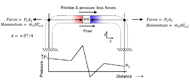
Figure 1: Simple force diagram for a fluid flow in a pipe
With flow through such a pipe, there are several forces acting on the fluid, including friction, pressure, gravity (which AFT Impulse neglects for force set calculations), normal forces from the pipe to the fluid, and forces due to redirecting the flow through the elbow’s directional changes (i.e., momentum changes). Only the forces which are axially aligned with the pipe will be considered. The forces upstream (1) and downstream (2) are strictly related to the static pressure and flow area at those points.
Using Newton’s second law, the momentum changes and forces can be related, and we can solve for the overall reaction force, Fx. Equation 1 below shows the complete force balance used by AFT Impulse.
|
|
(1) |

Note that Figure 1 does not show an area change at the valve, as shown below in Figure 2. If upstream and downstream pipe areas are identical, the momentum terms for the junction will always cancel out – in steady and transient conditions. AFT Impulse will account for this momentum change when it exists.
Steady State
For steady flow the velocity through a pipe is constant. Thus, the momentum terms will cancel out, leaving us with Equation 2 below.
|
|
(2) |

The force due to friction is equal to the pressure drop due to friction multiplied by the flow area.
|
|
(3) |

In steady state, the only source of pressure drop (at constant elevation) is friction. Therefore, the friction and pressure terms in Equation 2 cancel out, resulting in a net force of zero at steady state.
|
|
(4) |

Transient Conditions
What happens when we consider the above system in a transient case? We may have a large pressure wave propagate through this section of pipe, perhaps due to the instantaneous closure of a valve somewhere downstream:
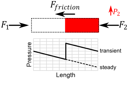
Figure 2: Simple case during a fluid transient, with a pressure wave travelling upstream
Pressure and flow in the pipe are no longer at steady state, meaning we must calculate every component of Equation 1. Additionally, the force due to friction varies over the force set, since flow is no longer constant along the length of the pipe. To accurately account for the friction force, we must sum the force from each section.
|
|
(5) |

The entire balance is calculated for a single time step, and must be repeated for every time step to determine the dynamic forces on the force set.
Force Components
In some fields, it is common practice to not include all terms of the force balance in calculations.
The simplest method is to look only at the forces due to pressure and momentum changes across junctions. The sum of forces in this force balance will not be zero even at steady state, as the friction and total momentum balance terms are not included in the calculation.
With AFT Impulse 7 and earlier, the option to ignore the friction and overall momentum terms was presented to users by default. Starting with AFT Impulse 8, those options were moved into the Advanced Parameters panel. Since those terms are often a significant part of a complete force balance, and are always real forces, it is strongly recommended to always include the momentum and friction force balance components, as they will give more accurate results.
Related Blogs


