New in Version 9
Analysis Setup
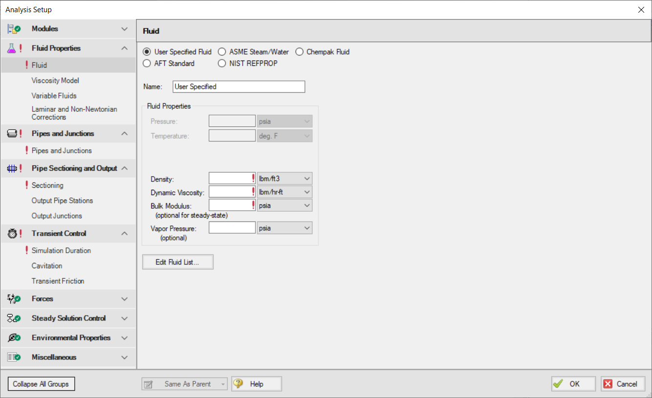
The Analysis Setup window consolidates windows for System Properties, Solution Control, Section Pipes, Transient Control, and Activate Modules all into one location. This allows users to activate and enable modules, specify fluids, change solution tolerances or iterations, and so on, all from a single window. For a list of windows that have merged into the Analysis Setup
Libraries
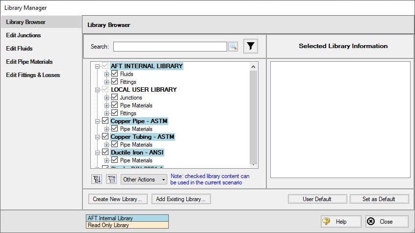
The database feature interface was completely overhauled to improve workability. The new system is called the Library Manager and significantly improves the ease and workability for users to browse and connect input information, now called libraries, into their model.
Gas Accumulator Updates
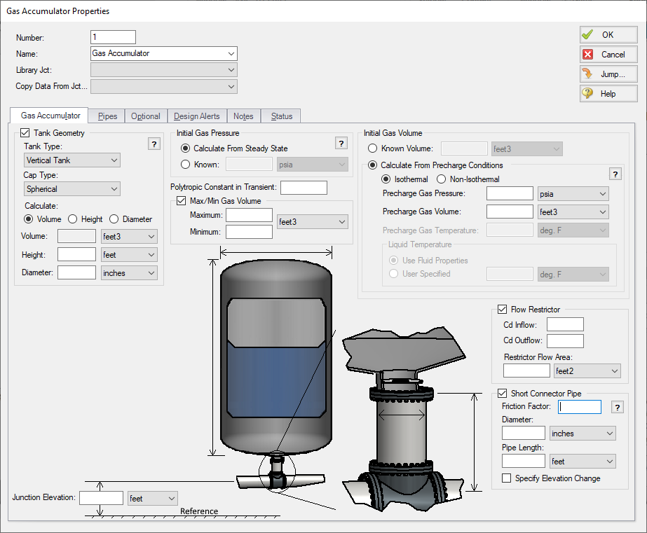
The Gas Accumulator Properties window has been redesigned, and several new features have been added as follows:
-
The tank geometry for the gas accumulator can now be defined, allowing the liquid level in the gas accumulator to be tracked, and limiting the gas volume accordingly
-
Additional options for defining the steady state gas accumulator volume have been added, allowing the thermodynamics for the steady state to be defined separately from the transient
Improved Organization of the Warnings in the Output
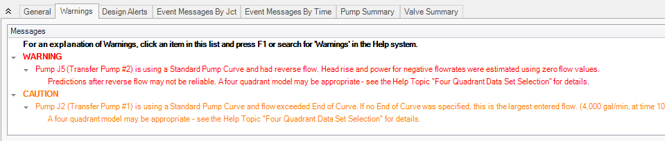
An improved display of the warnings and design alerts makes it easier to review and understand information in the following ways:
-
Critical Warnings, Warnings, and Cautions are color-coded and grouped by type in collapsible sections
-
Design Alerts are now shown on a separate tab in the General Section
-
Double-clicking messages will take user to the related pipe/junction in the Workspace
-
Warnings, Cautions, and Design Alerts are now displayed for all scenarios when using the Multi-scenario Output feature
More Improvements
-
Pipes/Junctions
-
Pipes can be defined as zero-length connectors to connect two junctions which are directly flanged together
-
Several new junctions have been added including the Bend, Orifice, Screen, and Venturi junctions
-
Submerged pump can now be defined using surface pressure and pump depth
-
Valve transients can be defined as open percent vs time
-
-
Workspace and Interface
-
Pipes and Junctions can be set the Same as Parent directly from the Workspace
-
Custom Unit names can be defined in the Unit System section of the User Options window
-
Pipe/Junction notes can be searched in Select Special
-
Special Conditions can be directly changed from the toolbar for junctions that have multiple special condition options
-
-
Output and Reporting
-
Show the number of warnings and design alerts in the batch run window
-
Design alerts are grouped together in the General Output section
-
New output parameters are available for the Relief Valve junction
-
-
Miscellaneous
-
Herschel-Bulkley non-Newtonian viscosity model added for representing Power Law fluids which have an apparent yield stress
-
New run time messages are shown in the Solution Progress window to help users adjust their model to decrease run time for the simulation
-
List Junctions that have Special Conditions change in Solution Progress window
-
Silent Batch runs can be enabled to prevent notifications from appearing over other active windows
-


