Pump As Turbine Configuration
The Pump as Turbine Configuration window is used to define the specific operation of a Pump as Turbine. It is opened by clicking Enter Curve Data from the Pump Properties window on the Pump Model tab when Pump as Turbine is selected.
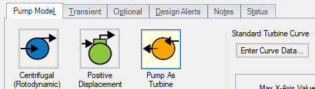
Figure 1: Enter Curve Data
Turbine Data
The first tab of the PAT configuration defines the PAT's most fundamental behavior - the turbine curves.
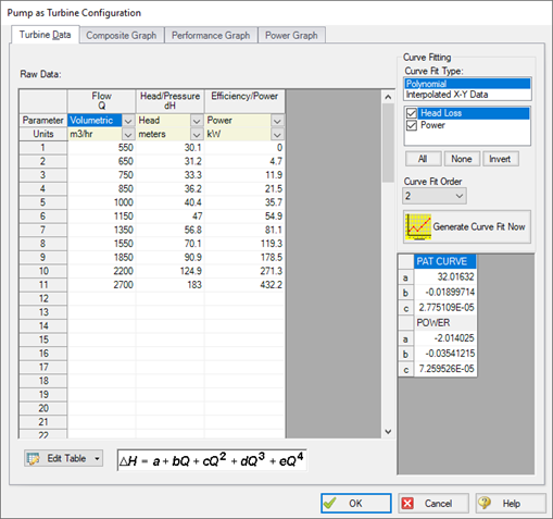
Figure 2: PAT Data
A PAT can have two curves defined:
-
Head or Pressure vs. Flow: Required. This curve is commonly referred to as the “turbine curve” and defines the head loss across the PAT at any given flowrate.
-
Power vs. Flow: Required. The power curve is used for two purposes for the PAT. First, it is used to determine the power generated while the pump is operating as a turbine. Second, it is used to determine if or when the pump and motor decouple.
Graphs
The following tabs display the curves that have been fit to the given data.
-
Composite Graph: Shows the curve-fit PAT Performance and Power curves.
-
Performance Graph: Shows the curve-fit PAT Performance curve overlaid on the raw data points. The solver will ignore the raw data points and operate on the curve fit.
-
Power Graph: Shows the curve-fit Power curve overlaid on the raw data points. The solver will ignore the raw data points and operate on the curve fit.
Related Topics
Related Blogs


