Pumps
The Pump junction allows you to model the pressure added to a system by a pump, and model many transient events involving pumps. Because all pumps are different, AFT Impulse does not provide any standard pump types. Pressure and flow data that describes the pump must be obtained from the manufacturer or from test data. To reduce repeated data entry, frequently-used pumps can be added to the Junction library.
Common Input Information
Like all junctions, pump junctions require a junction number, junction name, and inlet and outlet elevations. Similar to other junctions, pumps can have Design Alerts and Notes applied to them. They require two connecting pipes, unless the Submerged Pump option is enabled. Note that the direction of the connected pipes define what side of the pump is suction and which is discharge.
Pump Model
This tab requires the selection and definition of what type of pump the junction represents. There are two models currently available:
-
Centrifugal (Rotodynamic) - Represents a typical centrifugal pump where the head added to the fluid is related to the flow through the pump via a pump curve.
-
Positive Displacement - Represents a steady state approximation of a positive displacement pump. The flow is fixed to a constant value, and whatever head is necessary to obtain that flow will be supplied.
-
Pump As Turbine - Under reverse flow, centrifugal pumps can be made to generate power and act as a turbine. This option represents such a situation.
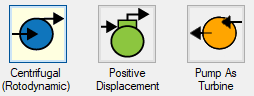
Figure 1: Pump Models
Variable Speed
This tab allows the speed of the pump to vary either by a fixed amount, or dynamically. These options are only available for a centrifugal pump.
-
Fixed Speed (%) - Directly modify the pump curve according to the Affinity Laws. The Pump Curve entered in Pump Configuration is always assumed to be the 100% speed curve.
-
Controlled Pump (Variable Speed) - Dynamically change the speed of the pump to meet a specified control setpoint. Instead of allowing the flow or head to vary with a fixed speed, the speed of the pump (and thus Pump Curve, according to the Affinity Laws) varies to meet a fixed flow or head. If modeling a suction or discharge pressure, control can optionally be enforced only if the value is above/below the setpoint.
Slurry De-Rating
Pump head degradation occurs when pumping solids. This is known as de-rating. This option is not available for the Pump as Turbine.
Transient
The pump junction allows several types of transients:
-
Without Inertia
-
None - Do not apply any transient, maintain the speed set throughout the transient, or modify the speed to meet the Variable Speed setpoint.
-
Speed vs. Time - Directly specify how the speed of the pump changes over time. This can be used to model startups, trips, or control transients.
-
With Inertia - Account for speed changes of a centrifugal pump impeller with an Inertial Model.
-
Startup - Along with the torque characteristics of the associated motor or driver, determine the speed change over time of the pump under an uncontrolled startup.
-
Trip - Determine the speed change of the pump under instantaneous loss of motor or driver torque, such as during a power failure.
-
PAT Transient
-
Full Load Rejection - Decouples the pump impeller from the motor and the PAT transitions from operating as a turbine to operating while decoupled.
For more information on transient data, including event transients, see Junction Transient Data.
All of the transient options need to know when to start with Initiation of Transient and allow the definition of a Transient Special Condition.
![]()
Figure 2: Pump Transients
Optional
There are several optional parameters that can be defined for a pump. Some of these are available to most junctions such as Initial Guesses, Display on Workspace, Design Factor, and Workspace Icon.
Also present are several pump junction specific options:
-
Special Condition
-
None - The pump operates normally.
-
Pump Off No Flow - The pump is shut off and blocked. This is identical to a closed valve.
-
Pump Off With Flow Through - The pump is shut off but allows flow to continue through. This is identical to a lossless connection.
-
Number of Pumps at This Location - Several pumps can be represented by one pump junction. This simplifies the model by reducing the number of pipes and junctions present, as well as automatically calculating the resulting composite pump curve. This option is not available for the Pump as Turbine.
-
Use Viscosity Correction - Pump performance changes if the system fluid viscosity is different than the pump test fluid viscosity. Viscosity Corrections allow the user to account for these changes. This option is only available for the Centrifugal Pump model.
Related Topics
Related Examples
Related Blogs
What Does “Head (HGL)” Mean for Submerged Pumps and Exit Pressures?


