Initiation of Transients
In general, transients can be initiated according to a certain time or according to certain events that happen in the system. These two categories are referred to as time based and event based transients. This is defined in the Initiation of Transient area of a junction's transient tab.

Figure 1: Type of transient initiation
It is helpful to consider the different time scales that are used when referring to the initiation of a transient, as shown in Figure 2.
Absolute and Simulation Time are often identical. The simulation Start Time is set in Simulation Mode/Duration panel to an Absolute Time of zero seconds by default, but it could be non-zero. In Figure 2, the Simulation Start Time is set to a value of 2 seconds – the entire Simulation Time timeline is shifted forward 2 seconds.
Event Time refers to the time data defined in Transient Data this could be equal to Simulation Time (and Absolute Time) depending on how the event is defined. For example, all three time bases will match for a pump trip event starting at the beginning of a simulation with Start Time equal to zero. However, the event may not start until a certain system condition is met and zero Event Time could be well into the simulation.
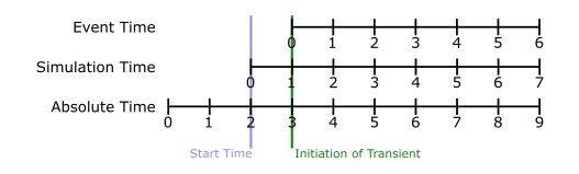
Figure 2: Time bases
Time
Time based transients modify a parameter directly according to Simulation Time.
For example, consider a valve closure transient. The valve starts to close at two seconds into the simulation, and the time it takes for the valve to close is one second. After that, the valve stays closed. To define this event with the Time option, the Start Time must be set to zero, and the Transient Data must look something like the data shown in Figure 3.
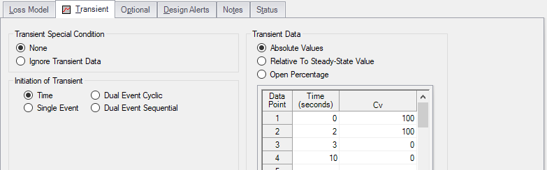
Figure 3: Defining a valve closure at a specific time
Single Event
Single Event initiated transients do not begin until a certain condition is met.
To completely define an Event, four parameters are required:
-
Event Type - What parameter is being considered to initiate the transient. See Table 1 below for a list of the possible Event Types.
-
Condition - The logical relationship between Event Type and Value (e.g. greater than, less than, etc)
-
Value - The specific magnitude of the Event Type parameter at Location
-
Location - Where in the model the Value should be observed
Given the same valve closure profile described in Figure 3, we can set the valve to remain open until (and if) the pressure at the inlet of P7 exceeds 100 psia. Note that the Transient Data is identical - but the initiation of the event may happen at a very different time.
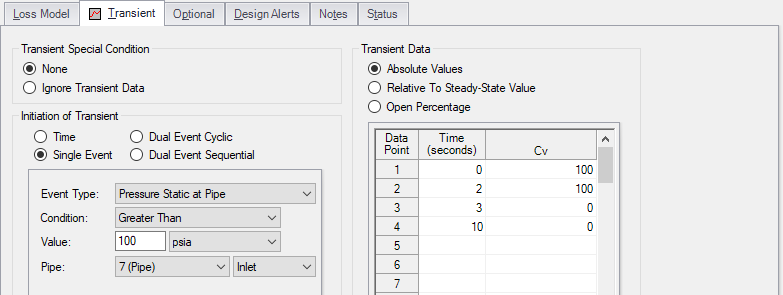
Figure 4: Event definition
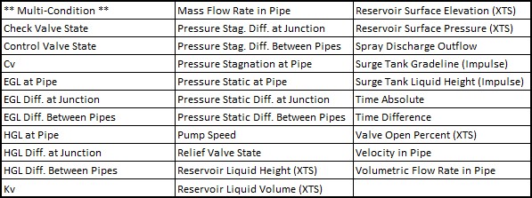
Table 1: Event types
Dual Event Cyclic
The Dual Event options, as the names imply, require the definition of two events. The definition for each event follows the same structure as a Single Event.
Dual Event Cyclic will continue monitoring both triggering events throughout the simulation and will apply the corresponding transient data when the conditions are met.
To continue with the valve example, we can define our valve not only to open when a pressure is exceeded, we can tell it to close when the pressure drops below a certain setting.
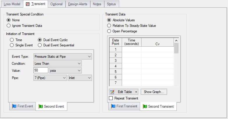
Figure 5: Dual Event set up. Note that a Second Event requires additional data for the Second Transient
Dual Event Sequential
Dual Event Sequential is nearly identical to Dual Event Cyclic. In fact, all of the required user input is the same.
The difference is that the two defined events are only applied once. That is – after the second event is complete, no more transients will be applied even if the conditions are met. One common situation where this is useful is tripping and restarting a pump in AFT Impulse. Pump tripping is often a one-time event rather than a function of normal operation, so it may not be desirable to define this as a cyclic event.
Junctions With Inherent Event Logic
There are three junction types in AFT Impulse which have built-in, or inherent, event logic. These are the check valve, relief valve and air valve. The user does not need to specify the nature of the events, and in fact is not allowed to.
The inherent event logic is very similar to the Dual Event Cyclic logic described previously.
-
Check valve - The check valve has two built-in events. The first is that it closes when backflow starts to occur. The second is that it reopens when sufficient pressure differential occurs. If the user does not enter a closing or opening transient in the check valve window, these transients are assumed to be instantaneous.
-
Relief valve - The relief valve has two built-in events. The first is that it opens when the cracking pressure is reached. The second is that it closes again when the pressure falls back below the cracking pressure. If the user does not enter an opening or closing transient in the relief valve window, these transients are assumed to be instantaneous.
-
Air valve - The air valve is very similar to the relief valve, and has two built-in events. The first is that it opens when the set pressure is reached. The second is that it closes again when the pressure rises above the set pressure and all gas is expelled.
Related Blogs


