Centrifugal Pump Overview
Standard Pump Curve
A Standard Pump Curve is required to model a centrifugal pump. This is the typical Head or Pressure vs. Flow information that will be available from any pump manufacturer. Certain features also require the definition of an NPSHR curve, and Power or Efficiency curves.
To enter these curves, click Enter Curve Data. Once this data has been defined, previews of the applied curves can be seen here.
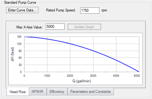
Figure 1: Standard Pump Curve
Performance Curve Used in Simulation
This section allows users to specify whether their pump will operate on the Standard Pump Curve they have defined, or on a Four Quadrant Curve. If it is known that the pump will never experience reverse flow, the Standard Pump Curve is sufficient. However, if it is possible for reverse flow to occur, the user should use the Four Quadrant Curve option, as it is important to accurately account for effects outside the Normal Pumping Zone (positive head, flow, and speed).
If the Standard Pump Curve is chosen, the only required input is the pump curve data, and that curve will always be used in the transient simulation. If reverse flow is encountered during the transient simulation, a warning will be presented, and the model should be adjusted accordingly. Impulse will attempt to estimate the effects of reverse flow by applying the zero-flow (deadhead) value to the fluid, but this is a rough estimate, and the users should modify the pump junction to use a four-quadrant curve if the pump sees large or sustained reverse flows.
If the Four Quadrant Curve is chosen, the user will be required to input the pump curve data, and select a Four Quadrant data set. To select a Four Quadrant data set, the user can either allow Impulse to Automatically Select the data set, or they can select a set manually. The Automatically Selected option will chose a data set based on the estimated specific speed of the user's pump.
When a Four Quadrant Curve is being used, the user has the option to allow Impulse to Prevent Reverse Rotation. This setting would reflect a physical device used to prevent the pump impeller from rotating in reverse, such as an impeller ratchet or similar. Reverse rotation can be prevented independently of reverse flow - enabling only this option will still allow reverse flow, but the impeller will not change directions under sustained reverse flow.
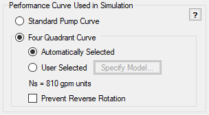
Figure 2: Performance Curve and related options
Model Combined Check Valve and Pump
This option adds a simple check valve to the pump junction to limit the reverse flow.
-
Forward Velocity to Close - The forward velocity under which the check valve closes. Once this velocity is reached during the simulation, the check valve will instantly close, preventing further flow. A check valve that closes under reverse flow requires a negative value to be entered for the Forward Velocity to Close.
-
Delta Head/Pressure to Re-Open - The check valve can re-open during the simulation. In order to do so, it must have a corresponding pressure or head difference across it defined. A positive value here indicates that the upstream pressure must be higher than the downstream pressure.
Note: The Combined Check Valve is limited in its ability to capture the potentially complex behavior of a check valve. Including the Check Valve within the Pump provides a convenient input method and also avoids modeling short pipes which lengthen the transient simulation. If the behavior of the check valve is critical to the system, it is recommended to use the Check Valve junction.
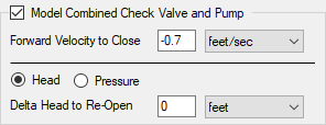
Figure 3: Model Combined Check Valve and Pump
Trimmed Impeller
These values allow representation of different impeller trims without the need to input new curves.
-
Ratio as Percent - This option assumes that the pump curve represents 100% trim. Entering different values adjusts the pump curve with the Affinity Laws.
-
Actual Impeller - Only available if Multiple Configurations are defined. In this case, a dimensional value for impeller size can be entered here.
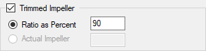
Figure 4: Trimmed Impeller
Submerged Pump
Represents a pump with a fixed head or pressure at suction. See Submerged Pump.
Flow Directional Behavior
A visual representation of the modeled pump is presented in the lower right of the properties window. This provides immediate feedback on what the various options represent. In the pump depicted in Figure 5, a Four Quadrant Curve is being used, modeled to prevent reverse rotation and have a check valve that closes at a negative forward velocity.
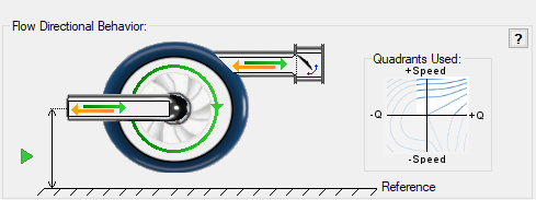
Figure 5: Visual diagram of model
Related Topics
Centrifugal Pump Configuration
Standard Pump Curve Waterhammer Theory
Related Examples
Related Blogs


