Annotations
Annotations are objects that can be placed on the Workspace to display customized text, express ideas via shapes or lines, or even to insert pictures into the Workspace. These are purely visual and do not affect results; their purpose is to communicate conceptual information about a system. They appear both in the Workspace and when printing from the Workspace.
New annotations are created using the Annotation Tool in the Toolbox. The Annotation Tool is located to the right of the Pipe Drawing Tool. With this tool, the user can draw a line or a shape on the Workspace. Shapes can display an image or text on the Workspace or can be used without text to display boundaries around various regions of the model.
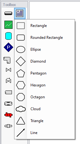
Figure 1: After clicking the Annotation Tool, select the shape for the new annotation
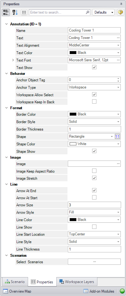
Figure 2: Annotation view for the Properties in the Quick Access Panel
After an annotation is placed on the Workspace, its properties are displayed in the Properties tab of the Quick Access Panel, where they can be edited. For an existing annotation, this tab can also be opened by double-clicking the annotation in the Workspace. Annotation styles can be set as default or restored to default settings by using the Defaults drop-down menu in the upper right of the Annotation properties area.
-
Annotations - Edit the annotation name, text content, text style, and text visibility in the Annotations section. The annotation name is not displayed on the Workspace but appears in the Layers Settings, where it can be used to communicate the purpose of the annotation.
-
Behavior - Configure how the annotation behaves in the Behavior section. Annotations can be attached to the Workspace, a pipe, or a junction. When attached to the Workspace, the annotation remains in the same location until it is moved. When attached to a pipe or junction, the annotation moves when the pipe or junction is moved.
Note: Whether an annotation appears behind or in front of another object is usually determined by the order of the Workspace Layers in which they are visible, but the Workspace Keep in Back toggle forces the annotation to appear below pipes and junctions regardless of layer order.
-
Format - Control the shape, as well as the shape style and visibility, in the Format section.
-
Image - Use the Image section to display an image within the annotation and control its appearance.
-
Line - Control the appearance of lines in the Line section. These settings apply only when the shape is set to be a line in the Format section. Shape color and border properties from the Format section are not used for lines.
-
Scenario - Control scenario visibility for annotations. Selecting the option next to Select Scenarios opens a window that lists all scenarios in the model. Scenarios can be toggled to display or hide the annotation in that scenario, providing control over which scenarios the annotation is visible in.
Interaction with Scenarios and Layers
Annotations exist globally in a model file and are visible in all scenarios by default. Their visibility is tied to layers and can be controlled for each layer in Layer Settings. In Layer Settings, annotations on a layer can be hidden or shown. The layer entry displays the annotation type, text, and the number of scenarios in which the annotation is visible. Layer Settings also provide a shortcut to the annotation’s Scenario property, allowing selection of the scenarios in which the annotation appears; this setting applies to the annotation itself, not to a specific layer.
Related Topics