Standard Layers
Standard Layers are the foundation of Workspace Layers to configure the display of data and objects on the Workspace. Standard Layers manage the styles, labels, and visibility of pipes, junctions, and annotations in a model. Standard layers are created from the New Layer by selecting the option for Blank Layer. All models are required to have at least one layer and new models will already have a layer called Layer 1 that is configured to display object numbers, names, and workspace symbols.
Layers can be configured to display both input and output information within the labels of objects on the Workspace. Object colors, sizes, and other formatting options can also be controlled through standard layers.
Layer Settings - Pipes & Junctions
The Layer Settings window can be accessed by double-clicking a layer, from the single gear icon on the right of each layer, or by selecting the layer and clicking the single gear icon on the Layers Toolbar.
The layout of the Layer Settings window is similar to Analysis Setup, with a number of groups listed on the left side of the window. Each group contains items that when selected change the content of the main panel area on the right.
![]()
Figure 1: The Show/Hide & Style panel allows the appearance and visibility of objects and their labels to be managed
The Pipes & Junctions group of the Layer Settings window controls the visual settings and visibility of objects for a given layer. Note that changes to this panel are made live in real time, and no Apply button is needed to apply the changes that you make.
Pipes and junctions are shown in two separate lists, which can be filtered. Multiple pipes or junctions can be edited at a time by selecting multiple objects in the list and using the Object and Label visibility icons, Color picker, and Size/Thickness modifiers at the top of each table. The usual tools for selecting pipes and junctions, including Workspace select and Select Special, are available. Pipes and junctions may also be edited individually with the visibility, color, and size options in each row next to the associated object.
At the top of the window, the color, pipe thickness, and junction size for any newly drawn objects can be configured. Note that color and icon style for new junctions are set via the Toolbox as they are specific to each type of junction. The default options for these settings are configured in the User Options, and can be loaded or reset from the Defaults button. Additional options allow varying pipe thickness based on pipe diameter, listing or hiding objects from other scenarios, and forcing labels to match object visibility. A tooltip is shown next to each of these check boxes with more information on its function.
Vary Pipe Thickness - Edit Variance
When Vary Pipe Thickness is checked, the thickness of pipes will vary based on the diameter of the pipe. The Edit Variance button provides additional configuration for the variance between pipe thickness and diameter.
The Minimum and Maximum sliders will limit the visible size that the pipe thickness can display. The Diameter Range Restriction can be enabled to set the range of diameters that determines the corresponding pipe line thickness. The Minimum and Maximum input sets the threshold for the smallest and largest line thickness displayed; any diameter outside of this range will also show the same smallest or largest pipe thickness respectively.
Layer Settings - Label Control
A label is text that is associated with a pipe or junction on the Workspace. Labels include both input and output parameters along with object names, numbers, and workspace symbols. Within the Label Control group, the Pipe Parameters and Junction Parameters items allow for the parameters associated with a layer to be customized. Both input and output parameters are shown in the list on the left. Parameters shown on the right are selected to be displayed on the layer. The order of parameters in the list dictates the order they will appear within the label on the Workspace. Some junction parameters are only shown for specific junction types; these are indicated by the junction icon shown next to the parameter. Input parameters will always be shown when added to the list on the right. While there is no separate output mode, output parameters are only displayed when the current scenario has output data available. When there is no output available, output parameters will be grayed out within the list, but their list position and units may still be edited.
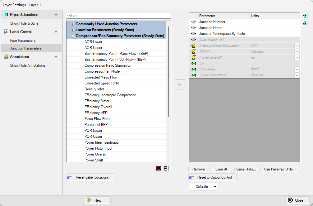
Figure 2: The Junction Parameters panel within the Label Control group of Layer Settings
The label shown for an object on the Workspace is a combination of defined label items from each visible layer, and the order of the items is determined by both the layer order and the order that parameters are listed within each layer. Label locations are defined globally, so the Reset Label Locations option will apply to all labels in all layers and all scenarios.
Label visibility is controlled from the Show/Hide & Style item. The Force Shown Labels to Match Shown Objects option forces the visibility of each label to match its object visibility as defined in the Pipes & Junctions group of the Layer Settings. By default, when a new layer is created this option will be enabled. By unchecking this option, the Label column in the Pipes and Junctions sections of the Show/Hide & Style panel will be enabled and the visibility for the label can be toggled independently from the object visibility.
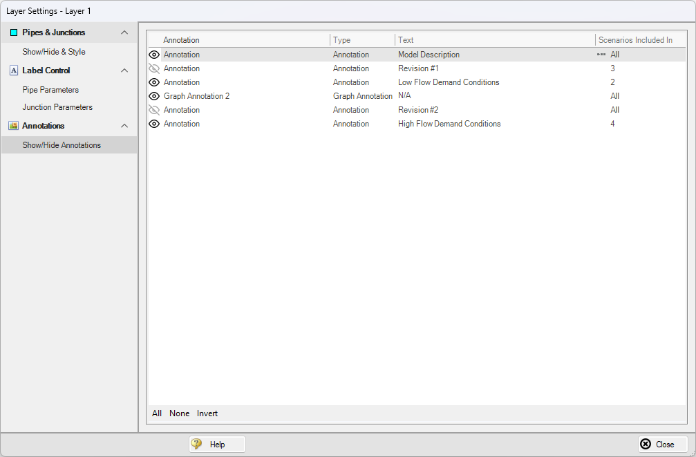
Figure 3: The Show/Hide Annotations panel shows all annotations that exist in the model file and allows their visibility to be controlled on a per-layer basis
The Show/Hide Annotations panel allows the visibility of annotations to be defined for the current layer and displays the visibility of each annotation in the current layer. Annotations are defined globally but can be configured to exist in specific scenarios. The Show/Hide Annotations panel will list the number of scenarios that an annotation exists in. If an annotation is chosen not to exist in a given scenario, it cannot be made visible in that scenario via layers. If the annotation is chosen to instead exist in that scenario, layers can then configure the visibility of the annotation. By hovering over an annotation, the three dots icon can be selected under the Scenarios Included In column to configure which scenarios the annotation exists in, but this is defined globally and not per-layer. Annotations can be edited from this list view by double-clicking them in the list to open the annotation in the Annotation Editor.