Pipe Sectioning and Output Panel
Before running a transient simulation, there are several pipe sectioning options that must be defined to section the pipes as described in Pipe Sectioning - Introduction to Method of Characteristics.
The user is required to specify the Sectioning item when the Transient Simulation Mode is selected. How the pipes are sectioned is controlled in the Pipe Sectioning and Output panel of Analysis Setup.
When the system has been defined, the Pipe Sectioning and Output panel will also show a Sectioning Summary which contains details of the sectioning including the estimated maximum sonic velocity, the estimated time step, and the estimated total steps. These numbers are only estimated values, as the actual values are determined after xStream gets results from the AFT Arrow Steady Solution. However, these estimates can help the user understand how many sections the system will have, and thus how long a run might take.
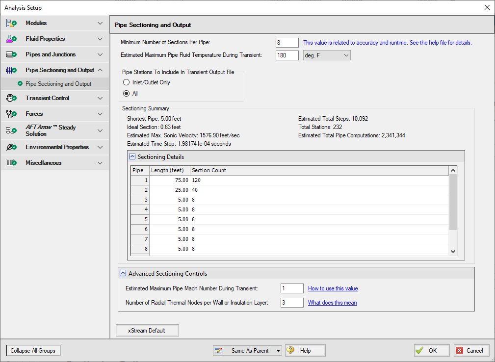
Figure 1: The Sectioning panel in the Analysis Setup window
Sectioning Options
-
Minimum Number of Sections Per Pipe - Defines the minimum number of calculation sections that will be used in each pipe in the model. Some pipes may use more than the minimum number of sections depending on the time step and maximum sonic velocity in the pipe. The ideal number of sections will vary based on the relative length of the shortest pipe compared to other pipes in the model, and the speed of transients in the model.
-
Estimated Maximum Pipe Fluid Temperature During Transient - Temperature used to determine the maximum sonic velocity for sectioning calculations. If the actual maximum temperature is not known, a higher temperature than expected should be used.
Transient Output Options
The Pipe Stations To Include In Transient Output File option controls how much data is saved to the file. By default all time steps for all pipe stations will be saved to file. The user may also set only the pipe inlet/outlet station data to be saved to file. Saving only the inlet and outlet stations to file will decrease the run time for the model, but also means that the user will not be able to plot the results at interior calculation stations for the pipes.
Numbering Convention for Pipe Sectioning
Once a pipe is broken into sections, computation takes place where the sections join together. These are called pipe stations. The total number of stations in a pipe is equal to the number of sections plus 1. The station at the beginning of the pipe is numbered zero.
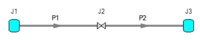
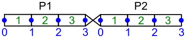
Figure 2: Computing Stations (blue) exist at the boundary of every section (green)
To observe parameters at the inlet or outlet of a junction, view the station adjoining the junction. In the above example, the inlet to the valve is P1, Station 3 and the outlet is P2, Station 0.
Advanced Sectioning Controls
-
Estimated Maximum Pipe Mach Number During Transient - Adjusts the MOC grid time step. An input value of 1 will ensure stability. For simulations with lower maximum Mach Numbers, reducing this input value can improve accuracy and runtime. If Mach Numbers higher than the Estimated Maximum Pipe Mach Number are encountered during simulation, the results will not be valid, and the simulation can become unstable or fail to converge. This can only be edited if advanced options are enabled.
-
Number of Radial Thermal Nodes per Wall or Insulation Layer - Defines the number of calculation nodes that will be used in the pipe wall and in each of the insulation layers when calculating radial conduction. The default setting of 3 calculation nodes per layer should be sufficient for most applications; However, changing the number of radial nodes may improve calculation stability if the heat rate changes rapidly across the pipe wall and insulation. See the topic on Transient Heat Transfer for more information on how the transient heat transfer calculations are performed.
Related Examples