Fundamental Equations
The continuity equation applied to a constant area pipe yields:
|
|
(1) |

The one-dimensional momentum equation applied to a constant area pipe yields:
|
|
(2) |

Assuming the pipe is straight over the computing section, Figure 1 shows the relationship between dx and dz:
|
|
(3) |

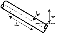
Figure 1: Relationship between distance along pipe (dx) and vertical elevation change (dz)
The fourth term on the left of Equation 2 accounts for pressure changes due to body forces. AFT Arrow models body forces due to gravity and due to rotation. If due to gravity, the default value of g in Equation 2 is the standard earth acceleration (i.e., 32.174 ft/sec2 or 9.81 m/sec2). This can be changed in the Environmental Properties Panel to any value you wish, which allows for modeling aerospace vehicles or non-terrestrial systems.
If a rotating system is modeled, the rotations per minute is input in the Environmental Properties Panel. You cannot model both gravitational and rotational accelerations at the same time. In practice, gas systems that rotate (such as turbomachinery) will be compact enough that elevation affects on pressure will be negligible.
In rotating systems, the junction elevations become distances from the rotation axis. The acceleration due to rotation becomes:
|
|
(4) |

where z is the junction elevation (distance from the axis) and w is the rotational velocity. This term is interchangeable with g in Equation 2, and henceforth g will be used with the understanding that it can refer either to gravitational or rotational acceleration as in Equation 4.
Also note that in rotating systems, the g level will increase as the distance from the centerline is increased. For each computing section, AFT Arrow uses the acceleration based on the arithmetic average of z inlet and z outlet.
From the equation of state for a real gas:
|
|
(5) |


