Junction Transient Data
(XTS Module Only) Many junction types can have active transient data specified. The junction types are listed in Table 1:
Table 1: Junctions that support transient data
|
Junction Type |
Type of Transient |
|
Flow rate and temperature |
|
|
Pressure and temperature |
|
|
Setpoint |
|
|
Speed, flowrate, control setpoint |
|
|
Temperature, Pressure, Volume, or Heat Rate |
|
|
Flow area |
|
|
K, Cv, or open percentage |
|
|
Heat Rate |
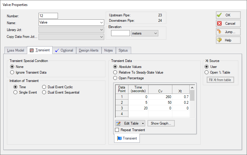
The active transient data is entered on the Transient tab (Figure 1). The type of data that can be entered for each junction type is listed in Table 1. If a junction does not have any active transient behavior, there is no need to enter any data on the Transient tab.
In most cases, transient data can be entered as absolute values or as a percentage of steady-state. The distinction is made when choosing between Absolute Values and Relative to Steady-State Value. Some junctions may have additional options, such as the Valve junction (Figure 1).
The first data point always needs to match the steady-state value which is usually entered on the tab at the far left. If, for example in Figure 1, the steady-state data for Cv of 260 is changed to 200, the transient data will also need to be changed. However, if in Figure 1 the Relative option is specified, the first data point would be 100%, and when the Cv is steady-state is changed from 260 to 200 there is no need to change the transient data since the first data point is still 100%. But it is now relative to a different steady-state value.

Figure 1: Example of junction transient data
Repeat Transient
If the transient data is periodic, you can enter the data for one cycle of the period and then tick the check box for Repeat Transient. This will cause the one cycle of transient data to be repeated once it has reached the end. The repetition will continue until the end of the simulation.
Transient Special Conditions
There may be occasions where, once having entered the transient data, you do not wish the transient to activate for a particular scenario. One option is to just delete the transient data. A second option is to specify the Transient Special Condition as Ignore Transient Data. In such a case, the data can be left in the window for future use, but will not activate during the run.
In Figure 1, there is an area called Initiation of Transient, and the selection is Time. This means that the specified transient is linked to the time of the simulation. Specifically, the valve transient data is activated as soon as the simulation is started. If the transient data was defined to have a constant Cv for one second, the valve does not start to close until the simulation time reaches one second.
Transients can also be initiated based on events. For instance, we can change the valve in Figure 1 to start closing when the pressure at some other system location reaches a certain level. Or maybe when a tank has reached a given pressure. In such a case, the time zero data in Figure 1 does not refer to the start of the simulation, but is relative to when the event occurs. If, for instance, the pressure never reaches the specified value, the valve never closes.
Related Examples
Related Blogs


