Convective Heat Transfer
There are 3 convective based models for pipe heat transfer:
-
Convective Heat Transfer - Represents a pipe thermally affected solely by convection.
-
Convective Heat Transfer and Heat Flux - Behaves the same as the Convective Heat Transfer model, but also includes the effect of an external heat flux such as radiation.
-
Convective Heat Transfer with Heat Tracing - Similar to the Convective Heat Transfer and Heat Flux model, but instead of applying the flux on the outermost surface of the pipe/insulation, the flux can be applied directly to the pipe. As the name suggests, this represents a device such as a heated wire. If the flux is not known directly, it is easy to determine based on Wire Turns and Length.
Defining the Convective Model
When one of the convective heat transfer models is selected, there are a number of items that must be defined:
-
Number of Insulation Layers - There can be up to three layers of insulation defined, in any combination of internal or external.
-
External Heat Flux - Only available if Convective Heat Transfer and Heat Flux is selected. A constant flux applied to the outermost layer of resistance.
-
Heat Tracing on Pipe (Flux) - Only available if Convective Heat Transfer with Heat Tracing is selected. A constant flux is applied at the outer wall of the pipe.
-
Ambient Conditions - The temperature and velocity of the fluid around the pipe. The fluid can be either air or water. These values are used for calculating the convection coefficient if correlation is selected as the convection Data Source. This correlation can be used for pipes over which boundary layers develop freely, free of constraints imposed by other surfaces. All of the external fluid properties are evaluated at the film temperature using data from the NIST REFPROP library.
-
Resistance Table - The table at the bottom of the window defines all of the resistance layers used in the thermal model.
-
Rows
-
Units - This special row defines the units of any value in the column below a cell.
-
Fluid Internal - The fluid itself has a convection coefficient that affects the transfer of energy to the pipe wall. By default, the Gnielinski Correlation is used to determine this value. Alternatively, the Dittus-Boelter Correlation can be used, or a User Specified value can be entered.
-
Pipe Wall - The wall of the pipe has a thermal conductivity that affects the heat transfer. The built-in pipe materials have thermal conductivity values defined, and this value is automatically selected. If a User Specified pipe is used, the conductivity will need to be entered.
-
Insulation - There can be several insulation rows, depending on the selection of Number of Insulation Layers. The Insulation can be selected from the Insulation library, in which case the conductivity is read from the library. User Specified insulation requires this value to be defined.
-
External - Convection occurring external to the pipe and any insulation layers. By default the Convection Coefficient is calculated with the Churchill-Bernstein Correlation. The Correlation can also be set to Free-Horizontal or Free-Vertical which requires only an ambient temperature, and no fluid velocity. The Free Horizontal and Free Vertical orientations are in reference to the orientation of the pipes. If the convection coefficient is known, a value can be entered by the user.
-
-
Columns
-
Apply - This can allow enabling/disabling of including certain layers in the calculation. This is useful for comparing states or scenarios without redefining the thermal model.
-
Conductivity/Convection Data Source - Specifies from where relevant information is attained. This can be a Library, Correlation, or User Specified.
-
Conductivity - Applies to the Pipe Wall and Insulation. If Data Source is a Library, the particular insulation must be selected. If User Specified, the conductivity must be entered. Note that obtaining the thermal conductivity from an insulation or pipe material library permits temperature dependent thermal conductivity to be employed. With this option, AFT Fathom dynamically selects the insulation thermal conductivity during model solving based on the local temperatures that exist. Conversely, user specified values are always constant.
-
Thickness - Applies to Pipe Wall and Insulation. If a Library is used for the Pipe Material, this value is automatically populated. All insulation layers require a thickness. If a Pipe Material is chosen on the Pipe Model tab, and that material has insulation data sets associated with it, an option is provided in the Conductivity/Convection Data Source column to select that insulation data set. The insulation data sets include the insulation thickness, and value is displayed in the thickness column.
-
HT Area Ratio - This represents any "extra" heat transfer area that may exist. For example, if the pipe has cooling fins this ratio would be larger than 1.
-
Convection Coefficient - Applies to Fluid Internal and External. Both values can be either Correlation or User Specified.
-
-
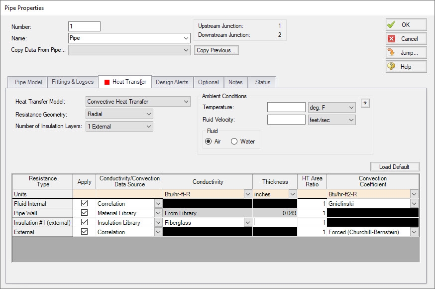
Figure 1: Convective Heat Transfer Layout
Modeling a Constant Wall Temperature
Assign an ambient temperature and disable the External Resistance by unchecking the box in the Apply column. This will force the outside wall of the pipe to be equal to the ambient temperature. Note that this differs from isothermal in that the fluid temperature can still change - only the outside wall of the pipe has a fixed temperature.
Related Blogs
Let the Heat Flow: Modeling Heat Transfer in Pipes in AFT Fathom and AFT Arrow


