Control Valve - ANS (English Units)
Control Valve - ANS (Metric Units)
Summary
This example will show how to use the ANS module to size a system based on pipe weight. For many systems the necessary cost data is not available to directly minimize cost, so minimizing system parameters such as weight or flow volume is useful. By minimizing parameters such as these we minimize pipe diameter, which directly correlates to minimizing pipe costs.
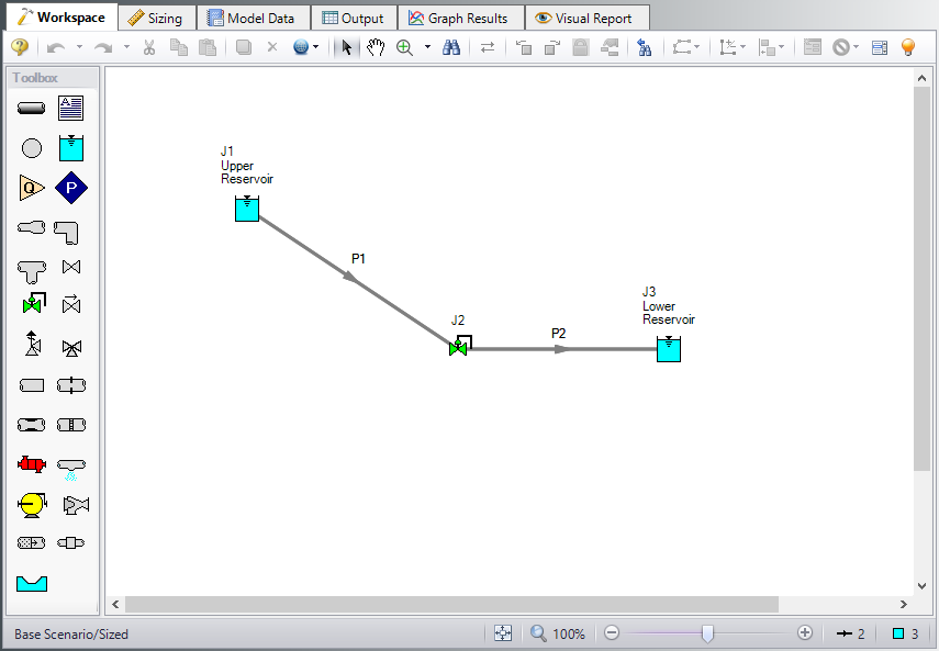
We will create a system that feeds water from an elevated reservoir to a lower reservoir at a specified flow rate. A control valve will be used to control the flow rate and can be placed anywhere within the line. We will need to determine what size of piping to use in order to achieve a minimum pressure drop of
Note: This example can only be run if you have a license for the ANS module.
Topics Covered
-
Sizing using pipe weight
-
Creating a Common Size Group
-
Defining Control Valve Design Requirements
Required Knowledge
This example assumes the user has already worked through the Walk-Through Examples section, and has a level of knowledge consistent with the topics covered there. If this is not the case, please review the Walk-Through Examples, beginning with the Beginner: Three Reservoir Model example. You can also watch the AFT Fathom Quick Start Video Tutorial Series on the AFT website, as it covers the majority of the topics discussed in the Three-Reservoir Model example.
In addition, it is assumed that the user has worked through the Beginner: Three-Reservoir Problem - ANS example, and is familiar with the basics of ANS analysis.
Model Files
This example uses the following files, which are installed in the Examples folder as part of the AFT Fathom installation:
Step 1. Start AFT Fathom
From the Start Menu choose the AFT Fathom 12 folder and select AFT Fathom 12.
To ensure that your results are the same as those presented in this documentation, this example should be run using all default AFT Fathom settings, unless you are specifically instructed to do otherwise.
Step 2. Open the model
Open the
Step 3. Define the Modules Panel
Open Analysis Setup from the toolbar or from the Analysis menu. Navigate to the Modules panel. For this example, check the box next to Activate ANS and select Network to enable the ANS module for use. A new group will appear in Analysis Setup titled Automatic Sizing. Click OK to save the changes and exit Analysis Setup. A new Primary Window tab will appear between Workspace and Model Data titled Sizing. Open the Analysis menu to see the new option called Automatic Sizing. From here you can quickly toggle between Not Used mode (normal AFT Fathom) and Network (ANS mode).
Step 4. Configure Sizing Settings
In this model we are going to perform sizing to minimize the pipe weight (therefore minimizing cost), while maintaining a minimum pressure drop of
To do this, first go to the Sizing window by clicking on the Sizing tab, or from the Windows menu.
A. Sizing Objective
The Sizing Objective panel should be selected by default from the Sizing Navigation Panel along the bottom of the window. Input the following:
-
Sizing Option = Perform Sizing
-
Objective = Pipe Weight
-
Option = Minimize
B. Sizing Assignments
On the Sizing Navigation Panel at the bottom of the window select the Sizing Assignments button.
In this case we are sizing a new pipeline, so we want to size all pipes in the model.
ØUnder Automatically Size select Always Include in Weight next to both pipes.
For this system it is required that both pipes be the same size. We will need to add both pipes to a Common Size Group to specify this. Do the following:
-
Click New above Pipe Grouping
-
Enter the a name Main Pipes and click OK. A new section will now appear with the Main Pipes group listed under Common Size Groups.
-
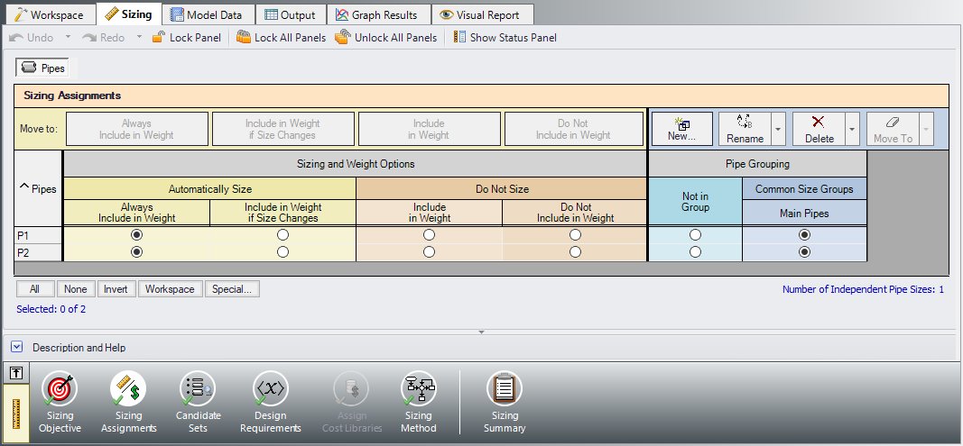
Add both pipes to this group by clicking the corresponding radio buttons (Figure 2).
Note that as many Common Size Groups as necessary can be created. Selection tools are available at the bottom of the window to help assign multiple pipes to a Common Size Group for larger models. Additionally, pipes can only be assigned to a group once they are set to be included in sizing.
C. Candidate Sets
Click on the Candidate Sets button to open the Candidate Sets panel.
-
Under Define Candidate Sets, click New.
-
Give the set the name STD Pipes and click OK.
-
In the Select Pipe Sizes window, choose Steel - ANSI from the drop-down menu if not already selected.
-
Make sure the Sort selection is for Type, Schedule, Class at the bottom of the window.
-
In the Available Material Sizes and Types on the left, expand the STD pipe sizes list.
-
Double-click each of the sizes from 1 inch to 12 inch to add them to the list on the right.
-
Now click OK.
The STD Pipes set will now appear as a Candidate Set at the top.
We now need to define which pipes will use this Candidate Set during the sizing calculation.
ØUnder Assign Candidate Sets to Pipes, set the Main Pipes Common Size Group to use the STD Pipes Candidate Set. The Candidate Sets are now fully defined and assigned to the appropriate pipes, as can be seen in Figure 3.
D. Design Requirements
Select the Design Requirements button.
For this model we only have one Design Requirement, which is for the minimum pressure drop across the Control Valve. To define this requirement:
-
Select the Control Valves button at the top of the window.
-
Click New under Define Control Valve Design Requirements.
-
When prompted, enter the name Min Pressure Drop.
-
Next to Min Pressure Drop in the table, select Pressure Drop Static as the Parameter.
-
Choose Minimum as the Max/Min option.
-
Enter 12.5 psid.
Now we need to apply the defined Design Requirement to the Junction.
ØCheck the box next to the Control Valve J2 in the Assign Design Requirements to Control Valves section.
Note: Control valves must always have a design requirement specified for the minimum pressure drop/head, or the maximum Cv/percent open at the valve to ensure that reasonable operating conditions exist at the control valve. If no Design Requirements are applied, the ANS module will allow the control valve to control to any pressure required to meet the control setpoint, even if this requires the control valve to add pressure to the system. To avoid this in the final solution, a Design Requirement should be applied.
E. Assign Cost Libraries
When the Sizing Objective has been defined as Monetary Cost, it is necessary to create and assign cost libraries for the automated sizing, which can be done in the Assign Cost Libraries panel. Since we have defined the objective as Pipe Weight, we will not need to assign any cost libraries, and this button is grayed out.
F. Sizing Method
Select the Sizing Method button to go to the corresponding panel.
Make sure Discrete Sizing is selected, since we are sizing based on commercial pipe sizes.
For the Search Method in a simple model such as this one, the MMFD or SQP method should be appropriate since there is only one Design Requirement, and only one pipe size is being varied. Choose the default Modified Method of Feasible Directions (MMFD).
Step 5. Run the Model
Click Run Model on the toolbar or from the Analysis menu. This will open the Solution Progress window. This window allows you to watch as the AFT Fathom solver converges on the answer. This model runs very quickly. Now view the results by clicking the Output button at the bottom of the Solution Progress window.
Step 6. Review the Sized Results
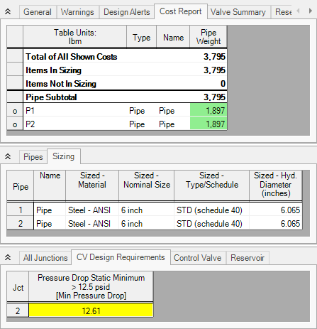
The output is shown below in Figure 4. We have shown all three sections of the output window with the General, Pipes, and Junctions sections. In the General Section, the Cost Report tab shows the minimized pipe weight for each of the pipes that were sized based on the design requirements.
In the pipe section, the Sizing tab is selected to show the final pipe sizes that were chosen. The ideal pipe size was found to be 6 inch pipe for this case. In the Junction section, the CV Design Requirements tab is shown. It can be seen that the Control Valve Design Requirement was met. The Design Requirement is colored blue, indicating that it was active in the final solution.
Step 7. Change the Control Valve Location
Now we would like to try something to further improve the system. For the first cut, we assumed that the control valve was in the middle of the pipe and that the pipes had to be the same size. If the pipes do not have to be the same length or size, we can further minimize the pipe weight and theoretically the cost of the piping.
To do this we will create another scenario.
-
In the Scenario Manager, create a child from the Sized scenario and name it Unequal Pipes. There should now be a check mark icon next to the scenario name to show that it is active.
-
On the Workspace open the Pipe Properties window for pipe P1 and change the length to 150 feet.
-
Open the Pipe Properties window for pipe P2 and change the length to 50 feet.
-
Go to the Sizing tab and click the Sizing Assignments button in the Sizing Navigation panel.
-
In the Pipe Grouping section of the table set both pipes to Not in Group. This will allow their sizes to be varied separately.
The scenario is now complete.
Step 8. Run New Scenario and Review Results
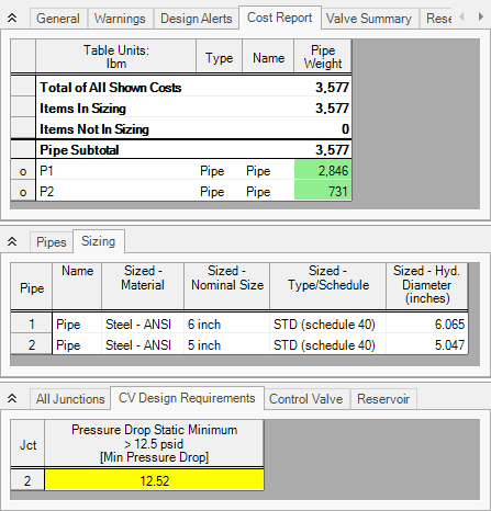
Now, we will run this scenario and see if we have minimized the pipe weight further. Select Run from the Analysis menu and allow the ANS module to size the system. When the analysis is complete, select Output to view the results.
The output window is shown below in Figure 5. We can see that pipe
Conclusion
This example has demonstrated how simple it is to perform an automated sizing to design a system for a set of requirements. Pipe weight may not be directly proportional to pipe cost but it can be implemented very quickly when cost data is not available.


