Housing Project - ANS (English Units)
Housing Project - ANS (Metric Units)
Summary
This example will size the pipes for a water supply system to a housing development. This example has three operating states. These states are the following:
-
No fire hydrants open, supply to each house is 10 gal/min with a minimum pressure of 60 psig.
-
North Hydrant open with 100 gal/min at 90 psig, supply to each house is 2 gal/min, no minimum pressure.
-
South Hydrant open with 100 gal/min at 90 psig, supply to each house is 2 gal/min, no minimum pressure.
For this example, we will evaluate all three conditions. First, we will use the ANS module to size the system assuming a requirement to use only one pipe size throughout. After this we will size the pipes assuming the pipes can be three different sizes.
Note: This example can only be run if you have a license for the ANS module.
Topics Covered
-
Using Dependent Design Cases to satisfy multiple operating modes for a system
-
Using the Scenario Manager to size a system for multiple sets of system requirements
-
Understanding the effects of Common Size groups on sizing
Required Knowledge
This example assumes the user has already worked through the Walk-Through Examples section, and has a level of knowledge consistent with the topics covered there. If this is not the case, please review the Walk-Through Examples, beginning with the Beginner: Three Reservoir Model example. You can also watch the AFT Fathom Quick Start Video Tutorial Series on the AFT website, as it covers the majority of the topics discussed in the Three-Reservoir Model example.
In addition, it is assumed that the user has worked through the Beginner: Three-Reservoir Problem - ANS example, and is familiar with the basics of ANS analysis.
Model Files
This example uses the following files, which are installed in the Examples folder as part of the AFT Fathom installation:
-
Housing Project Costs.cst - cost library for PVC - ASTM pipes
Step 1. Start AFT Fathom
From the Start Menu choose the AFT Fathom 12 folder and select AFT Fathom 12.
To ensure that your results are the same as those presented in this documentation, this example should be run using all default AFT Fathom settings, unless you are specifically instructed to do otherwise.
Step 2. Open the model
Open the
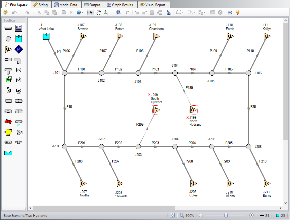
This example consists of a reservoir that supplies water to 10 houses and two fire hydrants. All the pipes in the system are Schedule 40 PVC pipe. The supply line to each house is set to 1 inch PVC. The automated sizing of this system will only be used to size the supply line from the reservoir, the neighborhood mains and hydrants.
As mentioned in the introduction, the supply to each house with no fire hydrants open (i.e., the Normal Flow case) is
-
Each house could be represented as an assigned flow with a minimum pressure constraint placed on the supply pipe to each house (as done here), or,
-
Each house can be represented as an assigned pressure with a minimum flow constraint placed on the pipe.
The first option was chosen because with either fire hydrant open, there is still an assigned flow on each house but there is no minimum pressure.
Step 3. Define the Modules Panel
Open Analysis Setup from the toolbar or from the Analysis menu. Navigate to the Modules panel. For this example, check the box next to Activate ANS and select Network to enable the ANS module for use. A new group will appear in Analysis Setup titled Automatic Sizing. Click OK to save the changes and exit Analysis Setup. A new Primary Window tab will appear between Workspace and Model Data titled Sizing. Open the Analysis menu to see the new option called Automatic Sizing. From here you can quickly toggle between Not Used mode (normal AFT Fathom) and Network (ANS mode).
Step 4. Configure Sizing Settings
For this system we will be sizing the neighborhood mains for three different operating cases, one for normal operation, and two different cases with hydrants in use. When modeling multiple design cases, the different cases need to be broken up into a primary design case, of which there is one, and dependent design cases, of which there can be any number.
The primary design case can be any of the design cases that are being addressed in your model. Typically, it will represent the primary operating condition of the pipe system. If it is not clear which case should be the primary case, just pick any of the cases and call that the primary one. Design cases other than the primary case are referred to as dependent design cases. This naming convention is used since the dependent design cases are built and defined by duplicating the primary design case, as will be discussed later. The normal flow case will be used as the primary design case, so we will start setting up the sizing settings based on the requirements for normal operation.
A. Sizing Objective
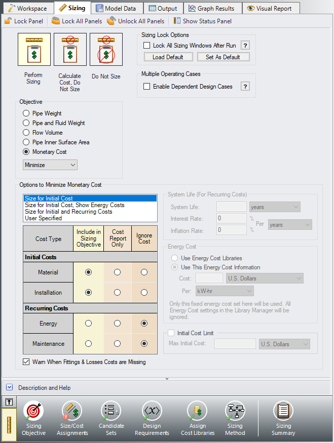
Go to the Sizing window and the Sizing Objective panel should open by default. For this analysis, we are interested in sizing the system considering the monetary cost for the initial costs only.
-
Set the Sizing Option to Perform Sizing, if not already.
-
For the Objective, choose Monetary Cost, and make sure Minimize is selected from the drop-down list.
-
Under Options to Minimize Monetary Cost, choose Size for Initial Cost. This will update the cost table to include both initial costs in the sizing calculation while ignoring the recurring costs.
The Sizing Objective window should now appear as shown in Figure 2.
B. Size/Cost Assignment
On the toolbar at the bottom of the window select the Size/Cost Assignments. For this scenario we will size the neighborhood mains, system supply line and hydrant supply lines assuming that they are all the same size. The supply lines to the houses must be 1" PVC so they will not be sized, but we will still calculate the costs, since we will need to purchase that piping as well.
-
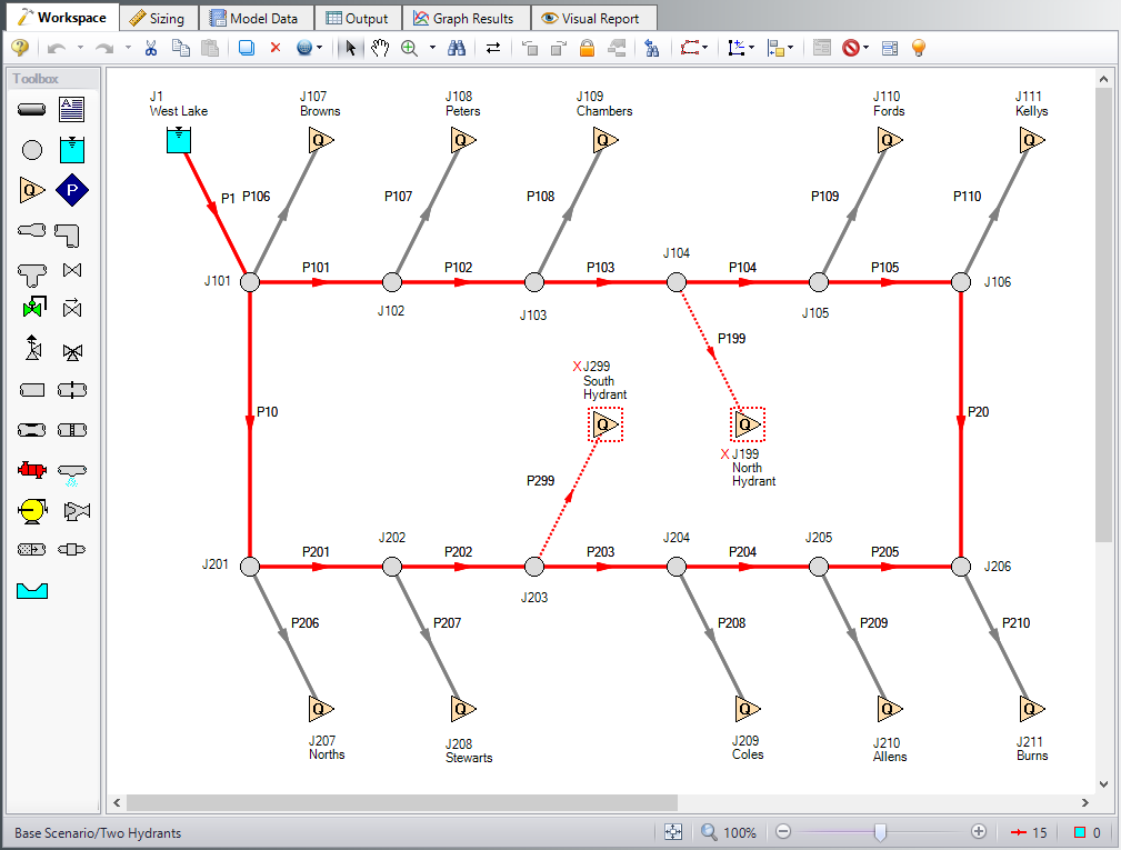
Go to the Workspace, and select the lines that will be sized as shown in Figure 3.
-
Right click the Workspace and choose Add Pipe(s) to Common Size Group, and select New Group. Give the group the name Neighborhood Mains. Click OK on the Information window that appears.
-
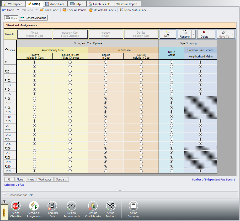
Return to the Sizing window. The neighborhood mains, supply line, and the hydrant supply lines should now all be included in the new pipe group, and should be moved to Always Include in Cost as shown in Figure 4.
-
Move each of the house supply lines to Do Not Size - Include in Cost. All of the pipes can be moved at once by using the shift key to highlight all of the rows, then clicking the Include in Cost button.
We are not considering any of the junctions as part of the sizing, so the Size/Cost Assignments are complete for now.
Note: Though the hydrant supply lines are closed in the primary design case, we need to include them in the Common Size Group so that they will be sized when we create the dependent design cases for the open hydrant cases.
C. Candidate Sets
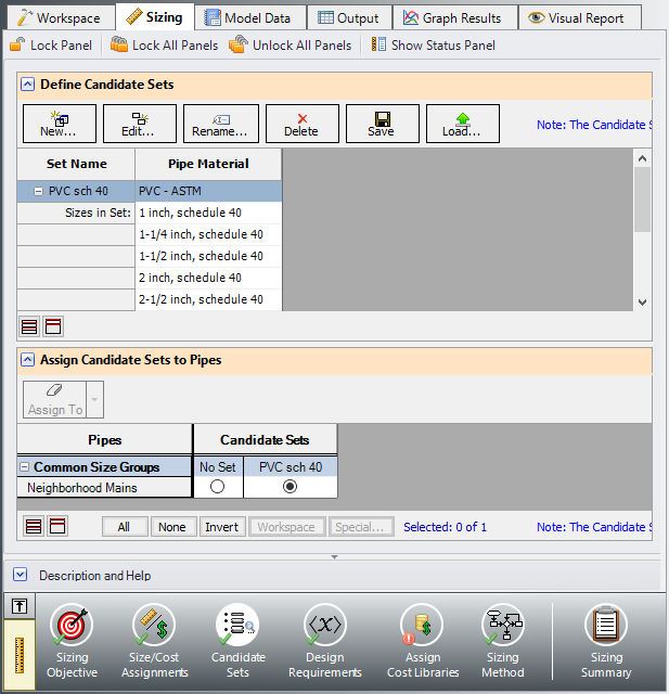
Click on Candidate Sets to open the Candidate Sets panel. In this case we will be considering schedule 40 PVC pipe within the range of 1" to 10".
-
Select New, and name the candidate set PVC sch 40.
-
Choose PVC - ASTM from the material list.
-
At the bottom of the window select to sort by Type, Schedule, Class (if not already selected).
-
Expand the schedule 40 type, then double click each of the sizes from 1 inch to 10 inch to add them to the Candidate Set.
-
Click OK to accept the defined set.
In the bottom section of the window make sure that the Common Size Group is assigned to use the new PVC sch 40 Candidate Set. The window should appear as shown in Figure 5.
D. Define Design Requirements
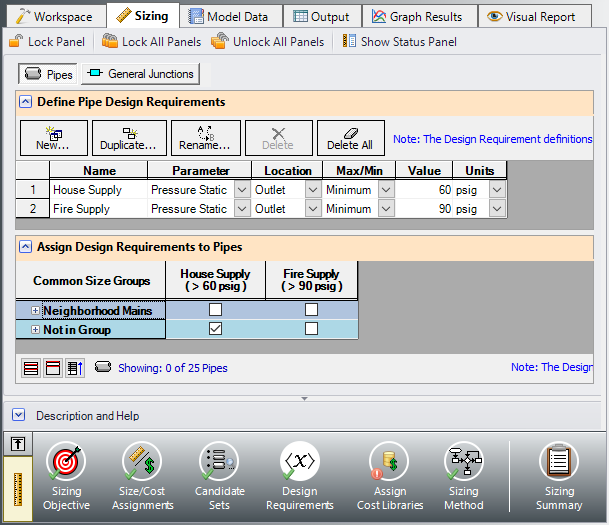
Select Design Requirements.
For the standard operation scenario the only design requirement is for the minimum supply pressure of
Click New again to create a second Design Requirement named Fire Supply specifying the Pressure Static at the Outlet of the pipe to a Minimum value of
In the bottom section of the window, make sure that the House Supply Design Requirement is applied to only the supply lines to the houses and no the Neighborhood Mains, as shown in Figure 6.
E. Assign Cost Libraries
Select Assign Cost Libraries. For this model the pipe cost library has already been created, but we will need to connect and apply it.
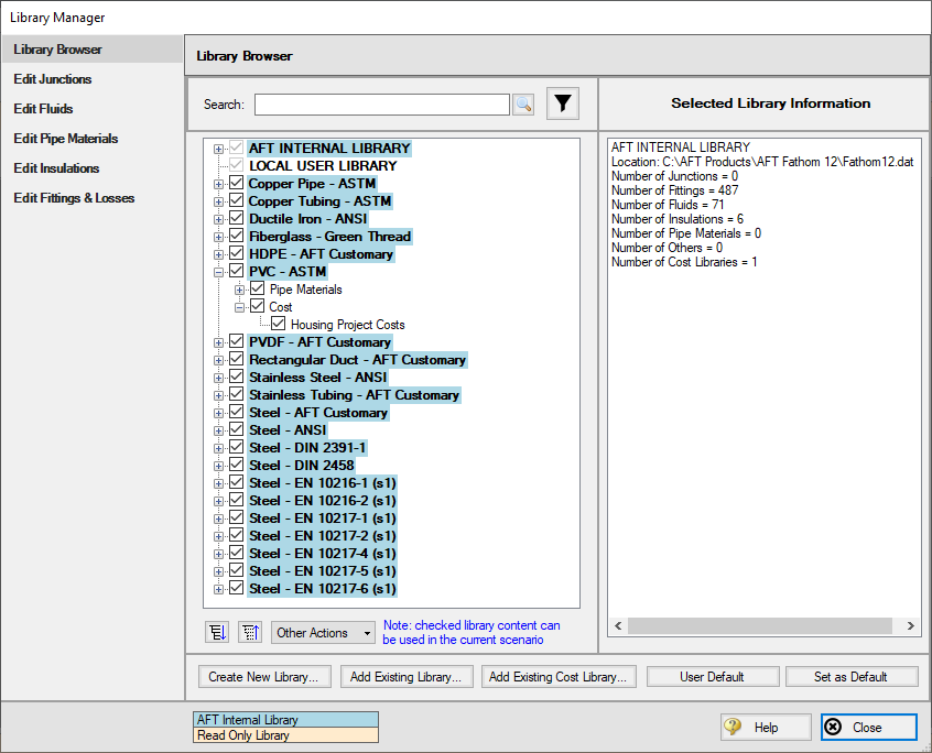
ØOpen the Library Manager by clicking the Library Manager button to see which libraries are connected.
This example uses a pre-built cost library for the pipes containing the PVC material costs. To connect the library do the following:
-
Click Add Existing Cost Library.
-
Browse to the Fathom 12 Examples folder (located by default in C:\AFT Products\AFT Fathom 12\Examples\), and open the file titled Housing Project Costs.cst.
The new library should now be visible in the list and be connected to the model, indicated with a box checked next to the name, as shown in Figure 7. The cost library for the pipes should appear with the name Housing Project Costs.cst and be indented under the PVC - ASTM library within the standard pipe material library list.
Once you have confirmed that the library is connected, click Close to exit the Library Manager.
Back in the Assign Cost Libraries panel for the Pipes, the Housing Project Costs library should be the only available cost library, and should be selected to show that it is being applied to the candidate set and to each of the house supply lines.
F. Sizing Method
Select Sizing Method to go to the Sizing Method panel.
Ensure that Discrete Sizing is chosen with the Modified Method of Feasible Directions (MMFD) for the Search Method.
G. Dependent Design Cases
We have now set up the system to be sized for the primary design case, but we will also need to account for the cases where either the north or south hydrant are in use. There are a few changes that occur for each of these cases where a hydrant is in use:
-
The flow rate at each of the houses decreases to 2 gal/min
-
The minimum inlet pressure for each of the hydrants must be 90 psig
-
The minimum pressure for each of the houses is removed
We will create two dependent design cases to account for the scenarios where the North Hydrant or the South Hydrant is open. To make the dependent design cases complete the following:
-
Go to the Sizing Objective panel and click the box next to Enable Dependent Design Case. A new button will now be available for the Dependent Design Cases panel in the Sizing Navigation panel.
-
Navigate to the Dependent Design Case panel. You should now see instructions displayed to create Dependent Design Cases, along with a summary table of dependent design settings. We will now need to use the Duplicate Special feature to create the dependent design cases.
-
Go to the Workspace and go to the Edit menu and choose Select All.
-
Go to the Edit menu again and select Duplicate Special, enter an increment of 400 and click the boxes next to Make Dependent Design Case and Clear Design Requirements (Figure 8). Click OK.
-
Move the duplicated pipes and junctions below the original ones on the Workspace to distinguish them from the Primary Design Case. Click Paste.
-
Select only the primary design case model and repeat steps 4 and 5 to create a second dependent design case (increment the pipe numbers by 1000 to avoid conflicting pipe numbers). There should now be two copies of the original model in the Workspace which will be used to represent the alternate operating cases.
-
Open the J599 and J1299 hydrants by selecting them and toggling the Special Condition to None so that the North Hydrant is open in the second case and the South Hydrant is open in the third case.
-
Use Global Junction Edit to change all 20 of the Assigned Flow junctions at the Dependent Design Case homes (junctions 500's, 600's, 1100's, and 1200's) to an Outflow of
-
In the Sizing window navigate to the Design Requirements panel. Assign the Fire Supply Design Requirement created earlier to pipe P599 and P1299 by checking the adjacent boxes.
Return to the Dependent Design Cases panel.
When Duplicate Special was performed with Dependent Design Case (DDC) selected, each of the duplicated pipes was created with a special type of grouping. For example, pipes 401 and 1001 were grouped with pipe 1 as DDC pipes (see Figure 10). This type of assignment allows the dependent design pipes to be sized, but to not be counted in the cost so that the cost will not be duplicated.
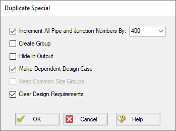
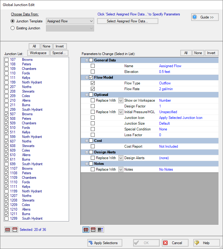
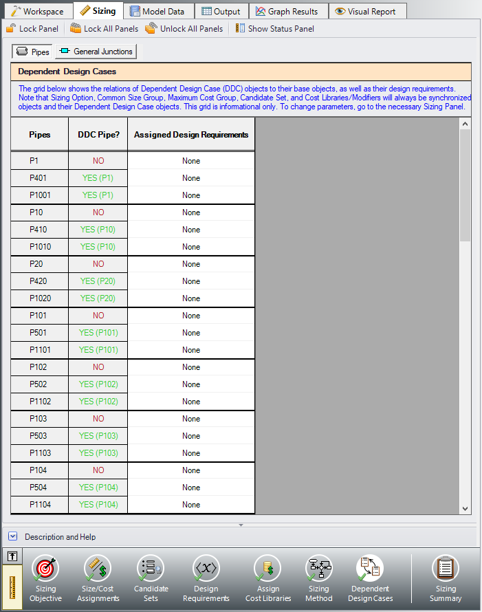
Figure 10: Pipes in Dependent Design Cases have a special grouping relationship with pipes in the primary case
Step 5. Run the Model
Click Run Model on the toolbar or from the Analysis menu. This will open the Solution Progress window. This window allows you to watch as the AFT Fathom solver converges on the answer. This model runs very quickly. Now view the results by clicking the Output button at the bottom of the Solution Progress window.
Step 6. Review the Sized Results
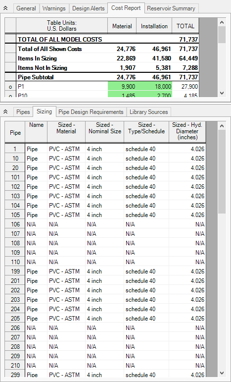
After the run finishes, examine the final pipe sizes calculated by the ANS module. The results for pipe size and overall cost are shown in Figure 11. One can see that the resultant size is 4-inch pipe. The lines to the houses are listed as N/A on the sizing output since they were not included in the sizing.
The cost for all sized pipes is
It should be noted that if we did not have monetary cost information for the pipes in this example, we could get nearly identical sizing results for this system by choosing a non-monetary objective. A monetary cost objective is primarily necessary in order to size equipment like pumps, control valves, etc. with the pipes.
Step 7. Increase the Independent Pipe Sizes
To increase savings in the system we can remove some of the pipes from the Common Size Group, which will allow them to be varied separately and increase the number of Independent Pipe Sizes for the model.
Let's create a child scenario to see how much savings can be found.
In the Scenario Manager, right-click the Two Hydrants scenario, click Create Child, and name it 3 Pipe Sizes. Navigate to the Size/Cost Assignments panel in the Sizing window. Unlock the panel if it has been locked and move pipe P1 to Not in Group. Lastly, create a new Common Size Group by clicking New, naming it Hydrant Pipes, and moving pipes P199 and P299 to the new group.
Run the scenario and go to the Output to view the results.
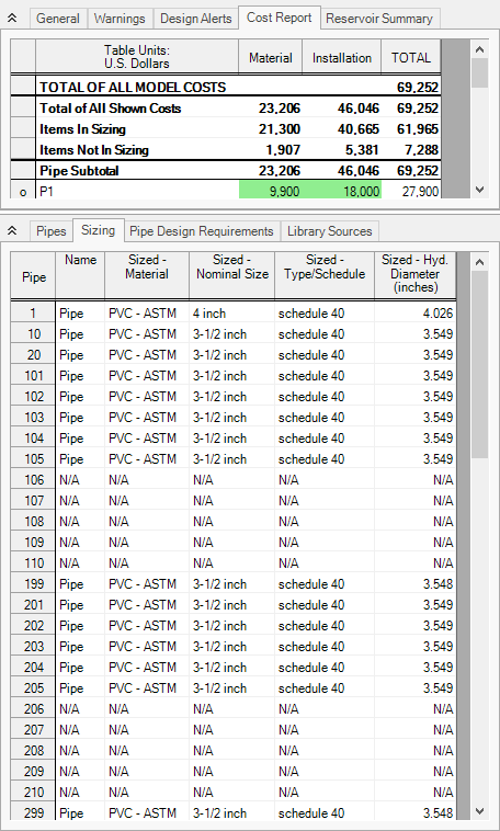
The Cost Report and pipe size results for the 3 Pipe Sizes scenario shown in Figure 12. The total cost is the cost per unit length for material and installation multiplied by the length of each section. The cost data does not include excavation costs. Even with these rough costs, significant savings can be achieved. If the developer is willing to use three pipe sizes, the savings will be approximately
With this example, we can see that the limitations placed on the system by Common Size Groups can impact the sizing results.
To obtain the best possible sizing results, one can ungroup all the pipes in the neighborhood and allow each pipe to be sized independently. While not shown here, it is possible to reduce the cost for this system to less than $59,000, a further reduction of $9,500.